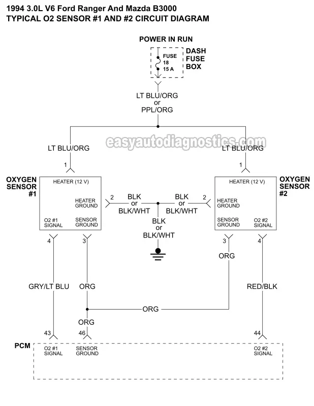
This typical circuit diagram of the oxygen sensors applies to the 1994 3.0L V6 Ford Ranger and 1994 3.0L V6 Mazda B3000.
Sensor #1 measure the oxygen content of the exhaust of engine cylinders 1, 2, and 3 (bank 1). Sensor #2 measures the exhaust of engine cylinders 4, 5, and 6 (bank 2).
O2 Sensor #1 Connector Pin-Out

| Pin | Wire Color | Description |
|---|---|---|
| 1 | LT BLU/ORG | Heater 12 Volts |
| 2 | BLK or BLK/WHT | Heater Ground |
| 3 | ORG | Sensor Ground |
| 4 | GRY/LT BLU | O2 Signal |
Oxygen sensor #1 is located on the right side (passenger side) of the engine. It measures the O2 content of the exhaust of bank 1 of the engine. Bank 1 houses cylinders 1, 2, and 3.
You can find the O2 sensor #1 heater element test here: O2 Sensor #1 Heater Element Test (1994 3.0L Ford Ranger And Mazda B3000).
O2 Sensor #2 Connector Pin-Out

| Pin | Wire Color | Description |
|---|---|---|
| 1 | LT BLU/ORG | Heater 12 Volts |
| 2 | BLK or BLK/WHT | Heater Ground |
| 3 | ORG | Sensor Ground |
| 4 | RED/BLK | O2 Signal |
Oxygen sensor #2 is located on the left side (driver side) of the engine. It measures the O2 content of the exhaust of bank 2 of the engine. Bank 2 houses cylinders 4, 5, and 6.
You can find the O2 sensor #2 heater element test here: O2 Sensor #2 Heater Element Test (1994 3.0L Ford Ranger And Mazda B3000).
More 3.0L Ford Ranger Tutorials
You can find a complete list of 3.0L Ford Ranger tutorials in this index:
Here's a small sample of the tutorials you'll find in the index:
- Tune Up And Torque Specifications 1991-1994 3.0L Ford Ranger.
- How To Test The TPS (1993-1994 3.0L Ford Ranger).
- How To Test The Fuel Injectors (1992-1994 3.0L Ford Ranger).
- How To Test The Fuel Pump (1992-2000 3.0L Ford Ranger) (at: troubleshootmyvehicle.com).

If this info saved the day, buy me a beer!

