TEST 2: Checking The Ground Circuit

So far, you have confirmed that the ignition control module (ICM) on your Quad-4 equipped vehicle is getting power (TEST 1).
Here we'll check that the Quad 4 ignition control module (ICM) is receiving Ground on the BLK wire of the ICM's harness connector.
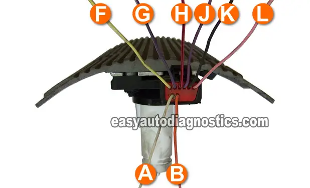
The BLK wire is the one that belongs to the K circuit of the harness connector.
These are the test steps:
- 1
Put the multimeter in Volts DC mode (or you can use a test light).
- 2
With the black multimeter test lead and a wire piercing probe, probe the ignition module connector's BLACK wire.
- 3
With the red multimeter test lead probe the battery positive (+) terminal.
- 4
You should see 12 Volts on the multimeter. Do you have 12 Volts? Or If you used a test light, it should come ON. Did the test light come ON?
Let's take a look at what your test results mean:
CASE 1: Your multimeter confirmed 12 Volts. This is good and confirms the ignition control module (ICM) has a good path to Ground.
Your next step is to is to confirm that the ignition control module (ICM) is receiving a crankshaft position signal from the crankshaft position sensor. For this test, go to: TEST 3: Testing The 7X CKP Signal.
CASE 2: Your multimeter DID NOT confirm 12 Volts. Double check your multimeter connections and make sure you're testing the correct circuit and repeat the test.
If your multimeter still does not register 12 Volts, then this indicates the ignition control module (ICM) is not being fed Ground and without this Ground, the ICM will not work.
Although it's beyond the scope of this tutorial, solving this issue will get the ignition control module to work again and the car should start again.
TEST 3: Testing The 7X CKP Signal

If you've reached this point, you have:
One: Confirmed that the ICM is getting power (TEST 1).
Two: Confirmed that the ICM is being fed Ground (TEST 2).
Now we're gonna' check that the ignition control module is getting a crankshaft position signal from the crankshaft position sensor (7X CKP sensor).
Checking the crankshaft position signal can be achieved by using a multimeter (or an oscilloscope).
To get into more specifics: You're gonna' probe the 2 wires that feed the crank position signal at the same time to get an AC voltage reading.
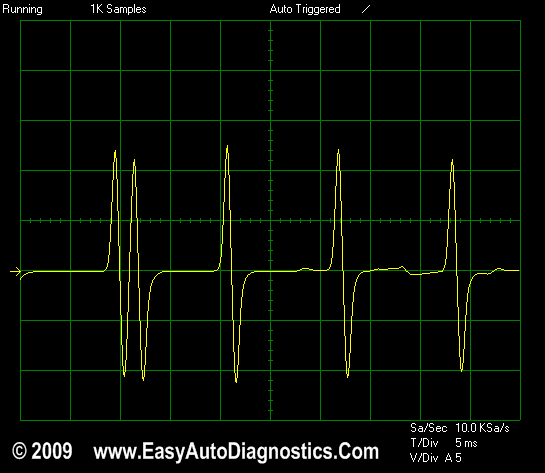
The two wires that feed the ICM the crankshaft position signal are the YELLOW wire (F circuit) and the PURPLE wire (J circuit) of the ICM's harness connector.
IMPORTANT: The battery must be in a fully charged condition for this test. Also, since you'll be working around a cranking engine; be careful, use common sense and take all necessary safety precautions.
Alright, these are the test steps:
- 1
With the connector disconnected or connected to the Quad 4 ignition control module (ICM).
- 2
Connect the test leads of the multimeter to either of the two wires with suitable tools (the polarity of the multimeter's test leads don't matter on this test).
- 3
Put the multimeter in AC Volts.
- 4
With the key ON and engine NOT CRANKING, you should have 0 Volts AC.
- 5
Have an assistant crank the engine while you observe the multimeter (or oscilloscope).
- 6
The multimeter's AC reading should fluctuate from 0.5 V AC to 1.3 V AC continuously as the engine is cranking (the minimum and maximum AC voltage reading attained will depend on the cranking RPMs. Engine temperature, oil viscosity and battery charge condition will have a direct effect on this).
Did the multimeter show an AC voltage reading? (Oscilloscope users see image below for full size picture of wave form)
CASE 1: Your multimeter registered the indicated Volts AC. This usually confirms that the crankshaft position sensor is good but not always.
There's one more test to make absolutely sure and this is to measure the resistance of the crankshaft position sensor. For this test, go to: TEST 6: Crankshaft Position Sensor Resistance.
CASE 2: Your multimeter DID NOT register the indicated Volts AC. If you have no AC voltage, recheck all connections and repeat the test again.
If your multimeter still does not register any AC Voltage, then this test result tells you that the crankshaft position sensor is defective and the cause of the 'no-spark no-start' condition your Quad-4 equipped vehicle is experiencing. Replace the crankshaft position sensor.
Here's a more detailed explanation:
- So far, you have:
- Confirmed that the ICM is getting power (TEST 1).
- Confirmed that the ICM is getting Ground (TEST 2).
- In this test, confirmed that the crankshaft position sensor is not creating/feeding a signal to the ICM.
Taking all of the above into account, you can confidently conclude that the reason the ignition control module (ICM) is not activating the ignition coils (and thus keeping the engine from starting) is due to the fact that the crankshaft position sensor is fried.
Take a look at the next subheading to find out more about the symptoms of a bad crankshaft position sensor.

Symptoms Of A Bad 7X CKP Sensor
In the beginning of this article, I talked a bit about the role of the 7X CKP sensor. If you're just landing onto this page from a search engine, take a look at the first part of this article. The info there will complement the following info.
When the crankshaft position sensor (known as the 7X CKP sensor in the GM service literature) goes bad on you car, normally you won't get a voltage A/C crankshaft position signal (from the crankshaft position sensor) at all.
In other words and to be a bit more specific, your multimeter will register 0 Volts AC. Also, the other clear indications that the 7X CKP sensor has fried, is that the 7X REFERENCE signal will not be generated by the ignition control module. This in turn will cause a no-spark condition in which none of the ignition coils will create spark and the PCM will not pulse any of the fuel injectors (no-fuel-injector-pulse condition).
TEST 4: Testing The 7X Reference Signal

Once the ignition control module (ICM) gets the crankshaft position sensor signal, it creates the 7X Reference signal.
The 7X Reference signal is the digital signal that the Quad 4 ignition control module (ICM) sends to the ECM so that the ECM can start activating the fuel injectors (among several things).
So, if you have reached this point in your diagnostic, you have:
One: Confirmed that the ICM is getting power (TEST 1).
Two: Confirmed that the ICM is getting Ground (TEST 2).
Three: Confirmed that the ICM is getting the crankshaft position sensor signal (TEST 3).
Now, in this test you'll check to see if the ICM is creating (and sending) the 7X Reference signal the PCM needs to start injecting fuel. If the ICM is not creating this signal, then you and I will know the ICM is bad and needs to be replaced.
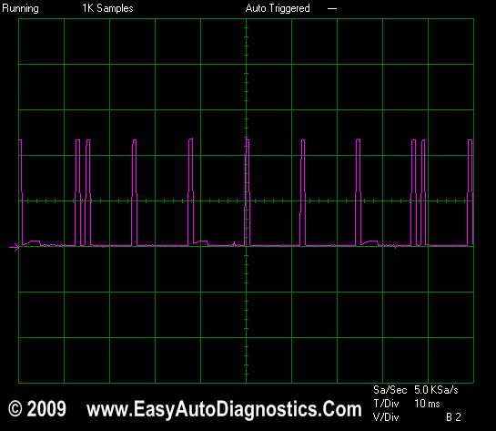
You're gonna' probe the wire to get a Hz frequency reading (if you're using a multimeter). This is the G circuit and is the PURPLE with WHITE stripe wire of the connector. Since you'll be working around a cranking engine; be careful, use common sense and take all necessary safety precautions.
IMPORTANT: To get the most accurate test result, the battery must be in a fully charged condition for this test. Also, to achieve this test, you'll need a multimeter that can read Hertz (Hz) Frequency (or an oscilloscope).
- 1
Put multimeter in frequency Hz mode.
- 2
With the ignition module connector connected to the ignition control module.
- 3
Connect the RED test lead of the multimeter to the PURPLE with WHITE stripe wire.
- 4
Connect the BLACK test lead of the multimeter to engine Ground.
- 5
with the key ON and engine NOT CRANKING, you should have 0 Hz.
- 6
Have an assistant crank the engine while you observe the multimeter (or oscilloscope).
- 7
The multimeter's Hertz reading should fluctuate from 29 Hz to 39 Hz continuously as the engine is cranking (the minimum and maximum Hertz reading attained will depend on the cranking RPMs. Engine temperature, oil viscosity and battery charge condition will have a direct effect on this).
Did the multimeter show the above Hertz readings? (Oscilloscope users see image below for full size picture of wave form)
CASE 1: Your multimeter registered the indicated Hertz values -Good, this test result means that the ignition control module is sending the 7X Reference signal to the ECM
To continue with your ICM diagnostic, your next step is to now confirm that the ICM is activating the two ignition coils that connect to it. For this test, go to: TEST 5: 1-4 & 2-3 Coil Control Signal.
CASE 2: Your multimeter DID NOT register the indicated Hertz values If your multimeter does not register a Hertz value(s), recheck all connections and repeat the test.
If your multimeter still does not register a Hertz value, the ignition control module is defective. Replace the ignition control module.
Here's why: So far you have:
- Confirmed that the ICM is getting power (TEST 1).
- Confirmed that the ICM is getting Ground (TEST 2).
- Confirmed that the crankshaft position sensor is creating/feeding a signal to the ICM (TEST 3).
- In this test, you have confirmed that the ICM is not creating a 7X Reference signal (the ECM needs to start activating the fuel injectors, etc).
Taking all of the above into consideration, you can conclude the ICM is defective and needs to be replaced.

Symptoms Of A Missing 7X REFERENCE Signal
This information compliments the basic operating theory found on the first page of this article: When the ignition control module (ICM) does not produce this signal, the fuel injection computer does not activate the fuel injectors, nor does it create the ignition coil control signal so that the module can start sparking the ignition coils.
You can further verify this (although it's not necessary) by disconnecting a fuel injector and installing a fuel injector Noid light into its connector. Have your assistant crank the engine while you observe the Noid light. There should be no pulses of the Noid light (in other words, the Noid light will not flash ON and OFF).
As stated above, if the module does not create this signal after you have verified that the crankshaft position sensor signal (7X CKP signal) is present (as done in TEST 3), the ignition control module is FRIED and needs replacement.
