
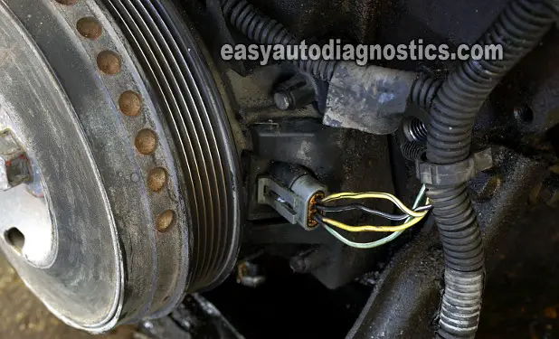
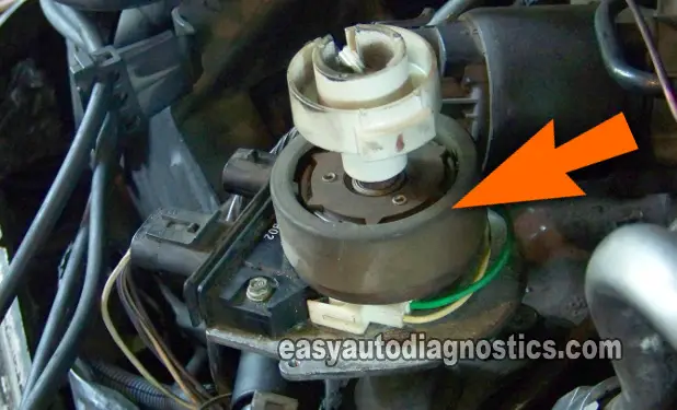
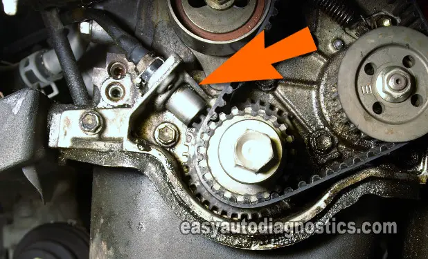
Crankshaft Position (CKP) sensors and Camshaft Positions (CMP) sensors used on cars and trucks today come in all sorts of different shapes, sizes and configurations.
All this variety might make you think that testing them is difficult and/or impossible. Well, nothing could be further from the truth since they can be easily tested with simple tools and testing techniques.
This article is a primer that will help you to learn and understand the essentials of testing the crankshaft position sensor (camshaft position sensors too). You'll learn basic working theory, do's and don'ts, what tools to use and how to test them, and a lot of other good stuff.
At the end of the article, in the section titled: Related Crankshaft Position Test Articles, I have included a list of test tutorials that will show you how to test the crank and/or cam sensor on several different makes (GM, Ford, Nissan, etc.) based on the info in this article.
Contents of this tutorial:
- How To Tell Them Apart.
- What Does A Crankshaft (Camshaft) Position Sensor Do?
- How Do The CKP And CMP Sensors Work?
- How Do The Two Wire Type CKP Sensors Work?
- A Digital Signal For A Digital Age.
- What ‘Excites’ The Sensor To Produce Its Signal?
- Where Are The CKP And CMP Sensors Located?
- Symptoms Of A Bad Crankshaft Position Sensor.
- What Tools Do I Need To Test The Crankshaft And Camshaft Positions Sensors?
- Do I Need An Automotive Scan Tool To Test The CKP And CMP Sensors?
- Do's And Don'ts When Testing CKP And CMP Sensors.
- What Does Each Wire (Circuit) In The Connector Do?
- Basic Circuit Description Of A Three Wire Sensor.
- Basic Circuit Description Of A Two Wire Sensor.
- What Are The Actual Testing Steps.
- Related Crankshaft Position Test Articles.
 You can find this tutorial in Spanish here: Lo Esencial De Los Sensores De Posición Del Cigüeñal Y Árbol De Levas (at: autotecnico-online.com).
How To Tell Them Apart
Another thing that can make testing the CKP and CMP sensors seem intimidating is the fact that every make and model rolling around on pavement uses a different type of position sensor.
For example, the Ford truck your neighbor might be driving will have a position sensor(s) that is (are) completely different in appearance than your GM (or Chrysler, or Honda, or Nissan or Suzuki, etc.) vehicle.
Not only that, but these sensors are called by so many different names like: Hall Effect sensor, CKP sensor, CMP sensor, Pickup Coil, Magnetic Pulse Generator, Variable Reluctor, and the list goes on with a few more names.
This may make it seem like every single one is tested in a different way. Well, the good news is that although they all differ from one another physically and are called so many god-knows-what names, they can usually be generalized into two basic categories: 2-wire type and 3-wire type. And this means that you only have to learn two specific testing methods.
So, before we dive into the rest of the article, I want to emphasize that the key to successfully testing and diagnosing all of the different crank sensors (and cam sensors) out there, is to know if they are either a two or three wire type!
Now in case you're wondering what I mean by two and three wire types, I'm referring to the amount of wires in their connector (of course there's always an exception to every rule, but more about this later).
Alright, let's jump into the next subheading and let's start learning more about this.
What Does A Crankshaft (Camshaft) Position Sensor Do?
I'll start by explaining the specific role that the Crank (and Cam) sensor play in the electronic ignition system of your car or truck.
By the way, this info applies to whatever make and model you may be driving, so whether it's a Ford, a Chevy, a Chrysler/Dodge/Jeep, a Nissan, a Honda, a Toyota, or whatever, this primer will help.
In a nutshell, the crankshaft position sensor's job is to help: 1) the ignition system produce spark and 2) the fuel system to start injecting gasoline into the cylinders. All this so that the vehicle's engine will start and stay running.
More specifically, the CKP sensor produces a signal that tells the fuel injection computer or the ignition control module the exact position of the cylinder pistons as they come up or go down in the compression cycle.
With this information the fuel injection computer or the ignition control module knows the exact time it has to make the ignition coil or ignition coils spark (not to mention when to start injecting fuel into the cylinders).
Lastly, this signal can be either an analog voltage signal of a digital DC voltage signal, but more about this a little later.
The camshaft position sensor is GENERALLY used in all modern sequentially fuel-injected engines to fine tune ignition timing and fuel injection timing after the vehicle has started.
Although this article concentrates on the basics of crankshaft position sensors, you can apply most of this info to the camshaft position sensors too.
Since the crankshaft position sensor's signal triggers the ignition module (or fuel injection computer) to start switching the ignition coil's Primary Current Ground path ON and OFF, I usually refer to the sensor's signal as the Triggering Signal.
Since the crank sensor (or cam sensor) is the one producing this Triggering Signal, I refer to it as the Triggering Device.
The signal that the ignition module (or fuel injection computer) sends the ignition coil for it to start sparking is the Switching Signal. So, guess what, the ignition module (or the fuel injection computer) is therefore the Switching Device.
Now, the ignition control module really doesn't send a physical signal (like the crank or cam sensor does to the Switching Device) to the ignition coil(s). Why?
Well, because the term ‘Switching signal’ is just a descriptive name for the turning ON and OFF of the primary current passing thru' the ignition coil.
As stated above, this turning ON and OFF only happens after the ignition module (or fuel injection computer) receives the crankshaft position sensor's signal. As you may already know, it's this action that causes the ignition coil to start firing spark.
You don't need to memorize all of these details, but it's very important to understand them. Why?
Well because understanding and knowing how one signal leads to the creation of another type of signal will help you to diagnose a ton of makes and models.
It'll also come in handy when you run across a specific testing step in your auto repair manual or in this site or any other that is not explained in painstaking detail (and you're feeling lost as to the ‘why’ of the test you just were asked to perform). Yes! Knowing this info will help you see the ‘light’.
How Do The CKP And CMP Sensors Work?
Since each of the two and three wire types of CKP (and CMP) sensors produce a different type of signal, I'll be explaining how both types work.
Now, I realize that you're not wanting to know how to build one from scratch or how to reverse engineer one, so I won't go into all of the details of what materials they're made of, nor the fundamentals of electromagnetism (that apply to these sensors) nor the minute details of how they produce their position signal (a good automotive technology textbook, or Wikipedia and/or the rest of the Internet is where you can find this information if you need it). You'll learn just the ‘nuts and bolts’ to test them in the real world.
I'll start with the two wire CKP and CMP sensors. These types of sensors are commonly known by several names: Magnetic Pulse Generator, Variable Reluctor, Pickup Coil, etc.
It doesn't matter what they're called or where in the car or truck they're located in, they are all tested with a multimeter in AC Volts mode. Why? Well, because the signal that these sensors generate is an analog voltage signal and this signal can only be measured in AC Volts mode on your multimeter (or oscilloscope).
How Do The Two Wire Type CKP Sensors Work?
When the Magnetic Pulse Generator type (remember, this is just one of the fancy names for the two-wire type sensors) is excited by the toothed disc it's in close proximity with, it starts to produce an analog voltage signal. This analog signal is created without the help of an external power source! As long as the engine is turning, either because it's cranking or running, the signal is being produced. When the engine is off, so is the sensor.
So then what is an analog voltage signal? As it applies to crank and cam position sensors, it's a signal that oscillates between lows and highs the whole time it's being produced WITHOUT ANY ABRUPT FALLING OR RISING EDGES. When the signal goes low, it never completely turns off. And when it goes high, it must come down again. This process is repeated over and over as long as the toothed disc is exciting it.
Looking at the oscilloscope waveforms below of three different crankshaft position sensors below will help you to put it all in perspective.
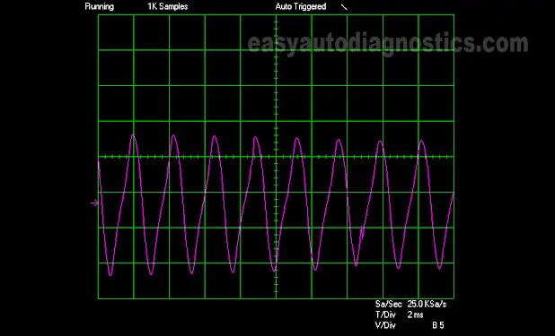
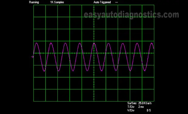
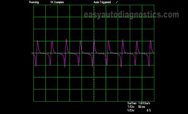
Did you notice in the above crankshaft position sensor signal waveforms that the AC analog signal produces a ‘wavy’ up and down line. Now, to test this signal you don't need an oscilloscope. But knowing what this signal looks like and how it behaves will help you to test it with a digital multimeter (an analog one will work too). So to further explain this concept I'm gonna' compare this analog signal to a light bulb that is cycled ON and OFF yet never completely turning off.
Let's imagine that we have a light bulb whose switch permits us to slowly apply power or slowly take it away but never allows us to completely turn it off. When you start applying the juice (to the light bulb), the bulb's brilliance starts to get stronger till you reach the maximum amount of power that can be applied. Then, you slowly start to take the power away, which results in its brilliance dimming. Now imagine repeating this cycle endlessly the whole time you need the room lit. Well, this is pretty much how the two wire type crankshaft position sensors produce their signal.
On a last note, you've probably noticed (in the slide show above) that each type of crankshaft position sensor waveform looks different from one another. And in case you've wondered why, well this is due to the amount, the shape, and how far spaced apart the teeth are on the ‘toothed disc’ that excites the sensor. This is something that you don't have to worry about when you're testing these crank and cam sensor with a multimeter.
So far in this article you've learned that all Crankshaft Position (CKP) sensors and Camshaft Position (CMP) sensors can be divided into two categories: two wire type and three wire type. Since I covered the two wire type of crankshaft position sensor (and by extension the camshaft position sensor) in the first part of this article, in this one I'm gonna' talk about the three wire type of crank sensor.
A Digital Signal For A Digital Age
OK, so far you've also learned that the two wire type (also known as a magnetic pulse generator type sensor, among several names) produces an analog signal. By now you may be wondering what type of signal the three wire type (Hall Effect type sensor) produces? The answer is: a digital signal. Now you might be asking yourself, "what the heck is a digital signal"?. Let's find out.
A digital signal is a DC voltage signal (remember that the analog signal is an AC voltage signal). This DC voltage signal looks and behaves completely different from an analog signal. Not only that, to produce this digital DC signal, the three wire type crank or cam sensor needs an external voltage power source (unlike the two wire type crank or cam sensor). When viewed in an oscilloscope's screen, it's displayed as a square wave, like the ones pictured below.
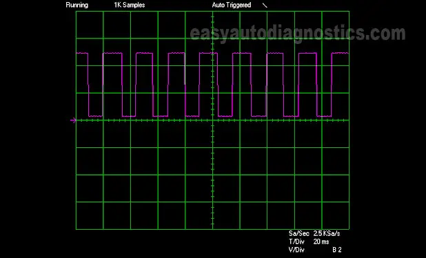
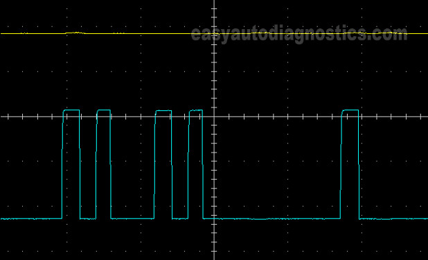
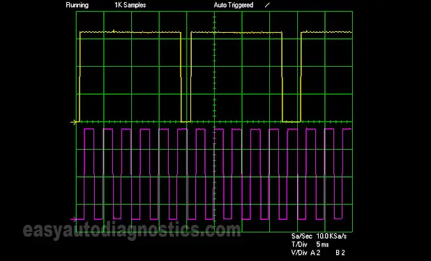
The digital signal that the three wire type (Hall Effect sensor type) produces is a true ON/OFF signal, very unlike the analog signal that the two wire type sensor produces. If we were to use the light bulb example from the previous page, the light bulb would turn on immediately (not gradually) and turn off abruptly (not gradually). This is what causes the sensor waveform to look squared instead of wavy. Also, this turning ON and OFF the signal happens the entire time the Hall Effect Position sensor is being excited by whatever toothed disc it's in close proximity to.
Now, in case you're wondering if you need an oscilloscope to test these crank and cam signals the answer is no. You don't need an oscilloscope and you definitely don't need an automotive scan tool to test the CKP sensor or CMP sensor signals. Now, having said that, the absolute best way to test/verify the presence of these signals is with an oscilloscope, but since most folks don't own one, this article concentrates on using a digital multimeter (that can read Hertz frequency).
OK, now for the really important ‘working theory’ part that you need to remember is that: the CKP and CMP digital signals can be measured with a multimeter either in DC Volts mode or in Hertz frequency mode or with an oscilloscope and that they need an external power source to create their signal. As a side note, a simple LED light can also be used to verify this signal (although this method is not a 100% foolproof way of diagnosing a CKP or CMP sensor).