How Do The CKP And CMP Sensors Work?
Since each of the two and three wire types of CKP (and CMP) sensors produce a different type of signal, I'll be explaining how both types work.
Now, I realize that you're not wanting to know how to build one from scratch or how to reverse engineer one, so I won't go into all of the details of what materials they're made of, nor the fundamentals of electromagnetism (that apply to these sensors) nor the minute details of how they produce their position signal (a good automotive technology textbook, or Wikipedia and/or the rest of the Internet is where you can find this information if you need it). You'll learn just the ‘nuts and bolts’ to test them in the real world.
I'll start with the two wire CKP and CMP sensors. These types of sensors are commonly known by several names: Magnetic Pulse Generator, Variable Reluctor, Pickup Coil, etc.
It doesn't matter what they're called or where in the car or truck they're located in, they are all tested with a multimeter in AC Volts mode. Why? Well, because the signal that these sensors generate is an analog voltage signal and this signal can only be measured in AC Volts mode on your multimeter (or oscilloscope).
How Do The Two Wire Type CKP Sensors Work?
When the Magnetic Pulse Generator type (remember, this is just one of the fancy names for the two-wire type sensors) is excited by the toothed disc it's in close proximity with, it starts to produce an analog voltage signal. This analog signal is created without the help of an external power source! As long as the engine is turning, either because it's cranking or running, the signal is being produced. When the engine is off, so is the sensor.
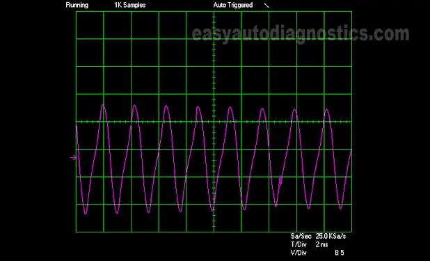
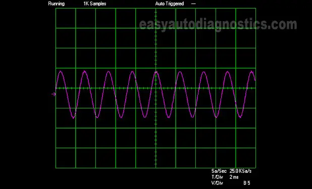
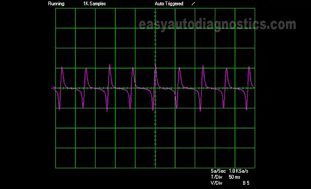
So then what is an analog voltage signal? As it applies to crank and cam position sensors, it's a signal that oscillates between lows and highs the whole time it's being produced WITHOUT ANY ABRUPT FALLING OR RISING EDGES. When the signal goes low, it never completely turns off. And when it goes high, it must come down again. This process is repeated over and over as long as the toothed disc is exciting it.
Looking at the oscilloscope waveforms below of three different crankshaft position sensors below will help you to put it all in perspective.
Did you notice in the above crankshaft position sensor signal waveforms that the AC analog signal produces a ‘wavy’ up and down line. Now, to test this signal you don't need an oscilloscope. But knowing what this signal looks like and how it behaves will help you to test it with a digital multimeter (an analog one will work too). So to further explain this concept I'm gonna' compare this analog signal to a light bulb that is cycled ON and OFF yet never completely turning off.
Let's imagine that we have a light bulb whose switch permits us to slowly apply power or slowly take it away but never allows us to completely turn it off. When you start applying the juice (to the light bulb), the bulb's brilliance starts to get stronger till you reach the maximum amount of power that can be applied. Then, you slowly start to take the power away, which results in its brilliance dimming. Now imagine repeating this cycle endlessly the whole time you need the room lit. Well, this is pretty much how the two wire type crankshaft position sensors produce their signal.
On a last note, you've probably noticed (in the slide show above) that each type of crankshaft position sensor waveform looks different from one another. And in case you've wondered why, well this is due to the amount, the shape, and how far spaced apart the teeth are on the ‘toothed disc’ that excites the sensor. This is something that you don't have to worry about when you're testing these crank and cam sensor with a multimeter.
So far in this article you've learned that all Crankshaft Position (CKP) sensors and Camshaft Position (CMP) sensors can be divided into two categories: two wire type and three wire type. Since I covered the two wire type of crankshaft position sensor (and by extension the camshaft position sensor) in the first part of this article, in this one I'm gonna' talk about the three wire type of crank sensor.


