How Does The MAF Sensor Work?
To be able to understand how to test a MAF sensor, it's always good to know how it works.
The most important thing that you need to know is that the MAF sensor signal is directly related to the amount of air the engine is breathing when it's running.
This tells us that the engine will breathe in more air at 2500 rpm than when it's idling at 900 RPM. Taking this into account, the output value (Volts or Hz) that the mass airflow sensor will generate, and that you can verify with a multimeter, will be greater at 2500 RPM than at 900 RPM.
Another very important thing to know, when testing a mass air flow sensor, is that we don't need to know the exact voltage value for certain engine RPM. What is important is that the MAF sensor signal should increase when you accelerate the engine and should decrease once you let the engine return to idle.
I can tell you, from personal experience, that in nine out of 10 cases when the mass airflow sensor fails, it simply stays stuck producing one specific voltage (or Hz) value no matter how much you accelerate the engine.
Testing The MAF Sensor With A Multimeter
Although MAF sensors will vary in their setup from one car to another, generally there are 3 basic test that are done to see if it has failed or not. These three tests are:
- Making sure the MAF sensor is getting power. Power is in the form of 10 to 12 Volts DC.
- Making sure that the sensor is getting Ground.
- Making sure that the MAF sensor is generating a signal that increases/decreases when the engine is revved up/returned to idle.
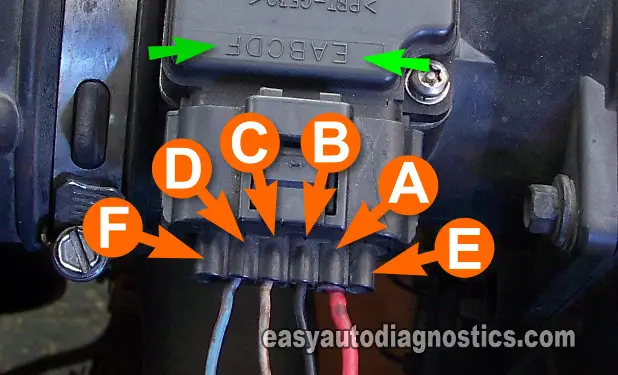
What complicates testing a MAF sensor is the fact that it could have 3, or 4, or 5 wires coming out of its connector. This requires using a wiring diagram (of the fuel system management system) to be able to know which wire is the one that feeds 12 Volts, which one is the that feeds Ground, and which one is the one that carries the MAF signal to the fuel injection computer.
Making sure the MAF sensor is getting 10 to 12 Volts: Generally, the mass airflow sensor get 12 Volts when the key is in the on position. These 12 Volts usually come from a fuse or a relay.
If the mass airflow sensor is being fed with 10 to 12 Volts, then the next step is to make sure it's getting around.
Making sure the MAF sensor is getting Ground: Depending on the make and model of your car, the mass airflow sensor will get Ground from the engine/chassis or through the fuel injection computer.
The only way to find out where the Ground is coming from is consulting a wiring diagram of the engine management system.
If the MAF sensor is getting Ground, then the next step is to make sure that it's generating a MAF signal.
Testing for the MAF signal: If the mass airflow sensor is getting power and Ground, then the next step is to make sure it's generating a correct signal. This signal will either be and analog signal or a digital signal.
If the mass airflow sensor is designed to generate an analog signal, then this signal will be a Volts DC signal and you'll be able to use your multimeter in its volt DC mode to see it.
If the mass airflow sensor is designed to generate a digital signal, then it'll be a Hertz (Hz) frequency signal and you'll need to use a multimeter that reads Hertz frequency.
The MAF signal has to be verified with the sensor connected to its electrical connector and with the engine running. This means that you'll need to use either a back probe or a wire piercing probe to access the signal within the wire.


