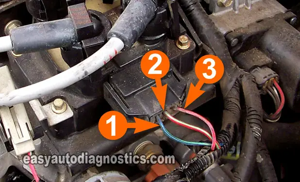
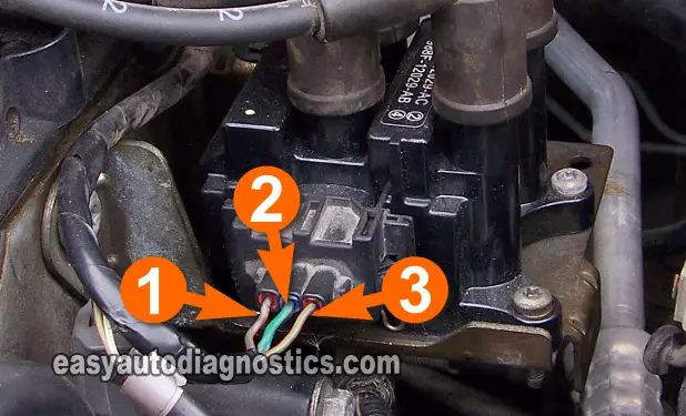
TEST 4: Testing The Power (12 Volts) Circuit
Testing the power circuit of the Ford coil pack can be done with a 12 Volt test light or a multimeter.
The wire that feeds power to the ignition coil is the middle wire of the coil pack connector. This wire is labeled with the number 2 in the photos above.
Also, it can be done with the coil pack connected or not to its connector. The following test steps assume that you'll test the power circuit with a multimeter and with the connector connected to the ignition coil pack.
Let's start:
- 1
Remove enough of the black electrical tape that's wrapped around the 3 wires of the connector to expose them for testing.
- 2
Disconnect the ignition coil from its connector.
- 3
Put the multimeter in Volts DC mode.
- 4
Probe the wire labeled with the number 2 with the red multimeter test lead (using an appropriate tool).
- 5
Connect the black multimeter test lead to the battery negative (-) terminal.
- 6
Have your helper turn the key to the ON position.
- 7
You should see 10-12 Volts on your multimeter.
Let's find out what your test result means:
CASE 1: The multimeter registered 10 to 12 Volts DC. This is the correct test result.
Then the next step is verify that the Switching signals are present, go to: TEST 5: Switching Signal For Cylinders 1 And 4 and then perform TEST 6: Switching Signal For Cylinders 2 And 3.
If the both Switching signals are not present (after testing them in TEST 5 and TEST 6), the most likely cause will be that the crankshaft position sensor is bad.
- If you need the test the crankshaft position sensor, I've written a tutorial that'll help you here: How To Test The Crankshaft Position Sensor (Ford 1.9L, 2.0L) (at: troubleshootmyvehicle.com).
CASE 2: The multimeter DID NOT register 10 to 12 Volts DC. Re-check all of your connections and retest.
If still no voltage is present, this result exonerates the coil pack. Repairing the cause of this missing voltage will solve the 'no-spark no-start' condition of your Ford (or Mercury or Mazda) car.
TEST 5: Switching Signal For Cylinders 1 And 4
In this test step, you're going to verify that the ignition coil (within the coil pack) that fires spark to cylinders 1 and 4 is being supplied with a Switching signal.
This test is done with the coil pack connected to its connector.
Alright, let's start:
- 1
Connect the black lead of the LED light to the wire identified with the number 1 in the image viewer.
This is the wire that feeds the Switching signal to the ignition coil (within the coil pack) that feeds spark to cylinders 1 and 4 simultaneously. - 2
Connect the red lead of the LED light to the battery positive (+) terminal.
- 3
Have your helper crank the car (the engine may start so be careful).
- 4
If the engine starts, have your helper turn it OFF.
- 5
If the Switching signal is present, the LED light will flash ON and OFF the whole time the engine was cranking and during the time it was running.
Let's find out what your test result means:
CASE 1: The LED light flashed ON and OFF the whole time the engine was cranking or running. With this test result you can conclude that the PCM is providing the Switching signal and the circuit is OK.
You can conclude that the ignition coil pack is bad if you have:
- Confirmed that the spark plug wires for cylinders 1 and 4 are not sparking (TEST 1).
- Confirmed that the ignition coil towers for cylinders 1 and 4 are not sparking (TEST 3).
- Confirmed that the ignition coil pack is receiving the 1/4 activation signal from the fuel injection computer in this test section.
CASE 2: The LED Light DID NOT flash ON and OFF the whole time the engine was cranking or running. This test result usually means that there's either an open-circuit in the circuit between the connector and the PCM or the PCM is fried (altho' a fried PCM is rare).
With this result you have eliminated the coil pack as the source of the misfire condition or no-spark condition.


