")
In this article, I'm gonna' show you how to test the throttle position sensor on your 2.2L Chevy Cavalier or 2.2L Pontiac Sunfire. So if the check engine light is on with diagnostic trouble codes: P0121, P0122, P0123 this is the article that is gonna' help you to solve them.
All of the steps of the throttle position sensor test are explained in detail and more importantly, you'll get a detailed interpretation of the possible results you'll obtain on your car.
Contents of this tutorial:
![]() You can find this tutorial in Spanish here: Cómo Probar El Sensor TPS Con Multímetro (GM 2.2L) (at: autotecnico-online.com).
You can find this tutorial in Spanish here: Cómo Probar El Sensor TPS Con Multímetro (GM 2.2L) (at: autotecnico-online.com).
NOTE: To see all 2.2L Cavalier and Sunfire Test Articles, go here: GM 2.2L Index Of Articles.
Symptoms Of A Bad TPS
You'll have the check engine light on, for sure, on your instrument cluster and one of several of the following symptoms:
- TPS diagnostic trouble codes (DTCs) stored in the vehicle's computer's memory.
- Really bad gas mileage. You know that it's not the price of gasoline that has you thinking that your 2.2L Chevy Cavalier or 2.2L Pontiac Sunfire is costing you more at the pump.
- Transmission does not shift out of second gear. Now, this doesn't happen very often, but it happens.
- No power and/or hesitation as you accelerate the vehicle. It feels like all of a sudden someone cut the power out momentarily as you step on the gas to get the vehicle moving.
How The Throttle Position Sensor Works
")
The throttle position sensor's job is to measure the angle of the throttle. So here, in a nutshell, is how the throttle position sensor works when you crank and start your 2.2L GM equipped vehicle:
- The fuel injection computer supplies 5 Volts and Ground to the throttle position sensor.
- Now, since the throttle is closed, the TPS (with power and Ground supplied) sends the PCM (Powertrain Control Module=Fuel Injection Computer) a DC voltage signal of about 0.9 to 1 Volt. This value is what the PCM associates with a closed throttle.
- Once you throw the car in drive and accelerate the car, the throttle opens and the throttle position sensor immediately sends this change of the throttle angle as an INCREASING voltage signal to the PCM.
- With this increasing voltage signal, the PCM knows it's time to inject more fuel, advance ignition timing, and a host of other things it has to do to keep your vehicle running optimally.
- As you let go off the accelerator pedal to slow down, the throttle plate closes and of course the TP sensor sends the info to the PCM as it returns to its base voltage signal, till the whole cycle begins again.
Pretty easy stuff? The cool thing is that the tests to check out the TP sensor's performance are as easy too. Now, since you'll be working in the engine compartment take all necessary safety precautions and use common sense. OK, enough of my yakking, let's get this show on the road, go to: TPS TEST 1: Testing The TPS Signal.
Where To Buy The TPS And Save
Disclosure: As an Amazon Associate, I earn from qualifying purchases. Buying through these links helps support this site at no extra cost to you. Thanks for your support —it really means a lot!
Not sure if the TPS fits your particular vehicle? Don't worry. Once you get to the site, they'll ask you for the details of your vehicle to make sure it fits. If it doesn't, they'll find you the right one.
TPS TEST 1: Testing The TPS Signal
Before you jump into the throttle position test on your Chevy Cavalier or Pontiac Sunfire, read the entire article first. I especially recommend reading the section: How The Throttle Position Sensor Works. Besides, there's a quiz at the end of the article.
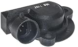
Also, depending on the year of your specific 2.2L GM vehicle, the TPS will be one of two designs (see image at the beginning of this tutorial), but they both use the same connector and so the colors (of the wires) will be the same (and more importantly the tests steps are the exact same).
OK, let's jump into this first test. Almost forgot to tell you that you're gonna' need someone to help you complete part of this test. This is what you'll need to do:
PART 1:
- 1
If the engine is cold, crank it up and let it run for about 20 minutes or till it reaches it normal operating temperature. By having a warmed-up engine, the more effective the test will be at finding a failing throttle position sensor (TPS).
- 2
With your multimeter in Volts DC mode and with the throttle position sensor connected to its connector, probe the sensor's dark blue wire. This is the wire that connects to the terminal labeled with the letter C in the illustration above.
- 3
Ground the black multimeter test lead on the battery negative (-) terminal and then have your helper turn the key ON but the engine OFF.
- 4
What your multimeter should read is about 0.5 to 0.7 Volts DC. If it doesn't, don't worry about it just yet, continue with the other steps.
PART 2:
- 5
Now, with everything still connected from test steps 1-4, open the throttle by hand till it reaches its full open position in a slow and deliberate way.
- 6
Your multimeter will register an increasing DC voltage till it stops at about 4.5 to 4.9 Volts DC (once the throttle is fully open).
- 7
Now, slowly close the throttle, while you keep your eyes on the multimeter. Your multimeter should show a decreasing voltage till it reaches the voltage you recorded in step 4.
PART 3:
- 8
Now, you'll need a helper for the next steps:
Your assistant needs to lightly tap the TP sensor with the butt of a screw-driver's handle (or something similar, and I want to emphasize the words 'lightly tap’) as you open and close the throttle once again.
What you are trying to confirm is if the tapping of the screw-driver on the TPS will have an effect on the voltage readings on the multimeter. The tapping SHOULD NOT have any effect on the voltage readings. - 9
Repeat step 8 several times to make sure of your multimeter test results.
Interpreting The Results
CASE 1: The multimeter registered a smooth increase or decrease in voltage. This result lets you know that the throttle position sensor is good and not the cause of the issue.
Now, if the throttle position sensor code keeps coming back, take a look at the heading: TPS Code Will Not Go Away for a few more suggestions as to what could be causing the TPS diagnostic trouble code (DTC).
CASE 2: The multimeter DID NOT register a smooth increase or decrease in voltage and you saw the voltage reading skip or go dead when tapping the TPS. This test result confirms, beyond any doubt, that the throttle position sensor (TPS) is bad. Replace the throttle position sensor.
CASE 3: The multimeter DID NOT register any voltage. This is not good, but does not condemn the TPS as bad yet. Two more things need to be verified first, which are power and Ground to the sensor. Go to: TPS TEST 2: Testing The 5 Volt Reference Signal.