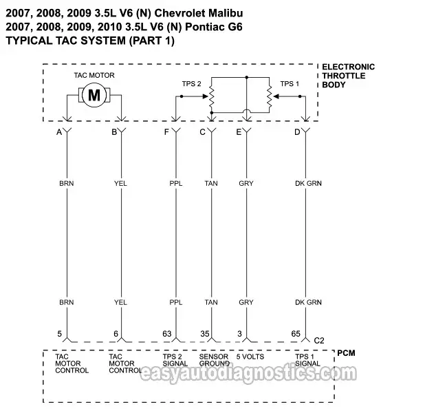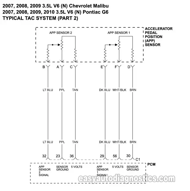
Here you'll find the wiring diagrams for the Throttle Actuator Control (TAC) system on the 2007, 2008, 2009 3.5L (N) Chevrolet Malibu and 2007, 2008, 2009, and 2010 3.5L (N) Pontiac G6.
The TAC system is made up of the electronic throttle body and the electronic accelerator pedal.
NOTE: The following simplified TAC system circuit diagrams apply only to the 2007, 2008, 2009 3.5L (N) Chevrolet Malibu and 2007, 2008, 2009, 2010 3.5L (N) Pontiac G6.
Contents of this tutorial at a glance:
If you need to test the electronic throttle body itself, check out this tutorial: Electronic Throttle Body Tests (2007-2009 3.5L Chevrolet Malibu And Pontiac G6).
NOTE: You can find the TAC system wiring diagram for the 2004, 2005, 2006 3.5L Chevrolet Malibu here: Throttle Body (TAC) Circuit Wiring Diagram (2004-2006 3.5L Malibu).
DIAGRAM 1: Electronic Throttle Body Circuit

NOTE: You can find an explanation of how the electronic throttle body works here: Electronic Throttle Body Basics (2007-2009 3.5L Chevy Malibu And Pontiac G6).
DIAGRAM 2: Accelerator Pedal Position (APP) Sensor Circuits

More 3.5L V6 Chevy Malibu Tutorials
You can find a complete list of 3.5L V6 Chevy Malibu tutorials here: GM 3.5L V6 Index Of Articles.
Here's a list of articles you'll find there:
- How To Test The Engine Compression (2004-2007 3.5L Chevrolet Malibu).
- How To Do A Cylinder Balance Test (2004-2007 3.5L Malibu).
- How To Test A Blown Head Gasket (2004-2007 3.5L Malibu).
- How To Test The MAF Sensor (2004-2008 3.5L Malibu).

If this info saved the day, buy me a beer!


