
Having a hard time trying to figure out if your engine's no-start problem is due to a bad ignition control module (ICM) or distributor pickup coil?
Well, I've got good news for you and it's that testing both of these components is surprisingly simple and can be done with just a few tools.
In this tutorial, I'll go over the steps to test both the ICM and distributor pickup coil to determine if either of them are the root cause of your engine no-start issue.
By the end of this guide, you'll have the knowledge and confidence to quickly diagnose the problem and get your vehicle back on the road again.
Let's get started!
Contents of this tutorial:
- Symptoms A Of Bad Ignition Control Module Or Pickup Coil.
- Ignition System Diagnostic Manual Download.
- Ignition Control Module Circuit Descriptions.
- Where To Buy The Ignition Control Module And Save.
- What Tools Do I Need To Test The ICM And Distributor Pickup Coil?
- TEST 1: Making Sure The ICM Is Getting 12 Volts.
- TEST 2: Testing The Ignition Coil Control Signal.
- TEST 3: Testing The Pickup Coil Signal.
- Distributor Pickup Coil Waveform.
- More 4.3L Chevy S10 Pickup, GMC S15 Pickup, And GMC Sonoma Tutorials.
APPLIES TO: This tutorial applies to the following vehicles:
- 4.3L Chevrolet S10 Pickup: 1988, 1989, 1990, 1991, 1992, 1993, 1994, 1995.
- 4.3L GMC S15 Pickup: 1988, 1989, 1990.
- 4.3L GMC Sonoma: 1992, 1993, 1994, 1995.
Symptoms A Of Bad Ignition Control Module Or Pickup Coil
If either the ignition control module (ICM) or the distributor pickup coil fails, the engine will not start.
This engine no-start will be due to a lack of spark, which is critical to igniting the air/fuel mixture in each of the six cylinders.
In some cases, the failure of either the ICM or the distributor pickup coil can be intermittent, meaning that it may work properly for the most part, but then suddenly stop functioning at other times.
In an intermittent engine no-start issue, it is crucial to remember that the ignition control module (ICM) and the distributor pickup coil must be tested when the engine is not starting, otherwise, if you test them when the engine is operational, the results will indicate that they are functioning properly.
Ignition System Diagnostic Manual Download
While this tutorial is a great resource, it doesn't include everything you need, such as a wiring diagram or a complete testing procedure in one place.
The digital download manuals (in PDF format that you can print) below include all this and more at an affordable price that won't break the bank. With this diagnostic manual, you'll have all the info you need to diagnose an engine no-start problem or an engine misfire problem caused by the ignition system. Order now and solve it today!
1995 4.3L S10 Pickup/Sonoma Ignition System No-Start Problem Diagnostic Manual
$5.99 USD
This digital download covers everything from an engine no-start problem caused by the ignition module, ignition coil or distributor pick-up coil, to misfire problems caused by the distributor cap or spark plug wires. Start diagnosing your 1995 4.3L V6 Chevy S10 Pickup/GMC Sonoma troubles with confidence today!
NOTE: This manual does not cover the externally mounted ignition control module.
The diagnostic manual includes these essential tools:
- Wiring diagrams.
- Component pin outs.
- Connector pin outs.
- Ignition system component part numbers.
- Firing order illustration.
- Complete step-by-step testing instructions with illustrations.
- Covers the 4.3L (VIN Z) TBI and 4.3L (VIN W) CPI engines.
This is a printer-friendly diagnostic manual! The illustrations are optimized to save you ink and ensure a hassle-free printing experience!
1994 4.3L S10 Pickup/Sonoma Ignition System No-Start Problem Diagnostic Manual
$5.99 USD
This digital download covers everything from an engine no-start problem caused by the ignition module, ignition coil or distributor pick-up coil, to misfire problems caused by the distributor cap or spark plug wires. Start diagnosing your 1994 4.3L V6 Chevy S10 Pickup/GMC Sonoma troubles with confidence today!
The diagnostic manual includes these essential tools:
- Wiring diagrams.
- Component pin outs.
- Connector pin outs.
- Ignition system component part numbers.
- Firing order illustration.
- Complete step-by-step testing instructions with illustrations.
- Covers the 4.3L (VIN Z) TBI and 4.3L (VIN W) CPI engines.
This is a printer-friendly diagnostic manual! The illustrations are optimized to save you ink and ensure a hassle-free printing experience!
1993 4.3L S10 Pickup/Sonoma Ignition System No-Start Problem Diagnostic Manual
$5.99 USD
This digital download covers everything from an engine no-start problem caused by the ignition module, ignition coil or distributor pick-up coil, to misfire problems caused by the distributor cap or spark plug wires. Start diagnosing your 1993 4.3L V6 Chevy S10 Pickup/GMC Sonoma troubles with confidence today!
The diagnostic manual includes these essential tools:
- Wiring diagrams.
- Component pin outs.
- Connector pin outs.
- Ignition system component part numbers.
- Firing order illustration.
- Complete step-by-step testing instructions with illustrations.
- Covers the 4.3L (VIN Z) TBI and 4.3L (VIN W) CPI engines.
This is a printer-friendly diagnostic manual! The illustrations are optimized to save you ink and ensure a hassle-free printing experience!
1992 4.3L S10 Pickup/Sonoma Ignition System No-Start Problem Diagnostic Manual
$5.99 USD
This digital download covers everything from an engine no-start problem caused by the ignition module, ignition coil or distributor pick-up coil, to misfire problems caused by the distributor cap or spark plug wires. Start diagnosing your 1992 4.3L V6 Chevy S10 Pickup/GMC Sonoma troubles with confidence today!
The diagnostic manual includes these essential tools:
- Wiring diagrams.
- Component pin outs.
- Connector pin outs.
- Ignition system component part numbers.
- Firing order illustration.
- Complete step-by-step testing instructions with illustrations.
- Covers the 4.3L (VIN Z) TBI and 4.3L (VIN W) CPI engines.
This is a printer-friendly diagnostic manual! The illustrations are optimized to save you ink and ensure a hassle-free printing experience!
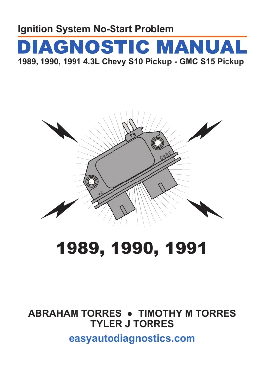
1989-1991 4.3L S10 Pickup/S15 Pickup Ignition System No-Start Problem Diagnostic Manual
$5.99 USD
This digital download covers everything from an engine no-start problem caused by the ignition module, ignition coil or distributor pick-up coil, to misfire problems caused by the distributor cap or spark plug wires. Start diagnosing your 1989-1991 4.3L V6 Chevy S10 Pickup/GMC Sonoma troubles with confidence today!
The diagnostic manual includes these essential tools:
- Wiring diagrams.
- Component pin outs.
- Connector pin outs.
- Ignition system component part numbers.
- Firing order illustration.
- Complete step-by-step testing instructions with illustrations.
- Covers the 4.3L (VIN Z) TBI engine.
This is a printer-friendly diagnostic manual! The illustrations are optimized to save you ink and ensure a hassle-free printing experience!
Ignition Control Module Circuit Descriptions
The ignition control module has three connectors. Here's a brief description of the circuits (wires) of all three connectors:
| CONNECTOR 1 | ||
|---|---|---|
| Terminal | Wire | Description |
| + | Pink (PNK) or pink with black stripe (PNK/BLK) | 12 Volts (input from ignition switch) |
| C | Pink (PNK) | IC Control Signal (output to ignition coil) |
| CONNECTOR 2 | ||
|---|---|---|
| Terminal | Wire | Description |
| B | Tan with black stripe (TAN/BLK) | 5 Volts (input from ECM above 400 RPM). |
| E | White (WHT) | ICM control signal (input from ECM above 400 RPM). |
| G | Black with red stripe (BLK/RED) or red with black stripe (RED/BLK) | Ground. |
| R | Purple with white stripe (PPL/WHT) | Fuel control circuit. |
| CONNECTOR 3 | ||
|---|---|---|
| Terminal | Wire | Description |
| N | Yellow (YEL) | Pickup coil signal. |
| P | Green (GRN) | Pickup coil signal. |
Where To Buy The Ignition Control Module And Save
The following links will help you comparison shop for the AC Delco and after-market ICM and distributor pickup coil:
- AC Delco - D1960A Ignition Control Module (at: amazon.com).
- Standard Motor Products - LX339 Ignition Control Module (at: amazon.com).
Disclosure: As an Amazon Associate, I earn from qualifying purchases. Buying through these links helps support this site at no extra cost to you. Thanks for your support —it really means a lot!
What Tools Do I Need To Test The ICM And Distributor Pickup Coil?
You don't need expensive diagnostic tools to test the ICM or the distributor pickup coil. The two most important tools you'll need are:
- A multimeter.
- An LED light.
You'll also needs some basic hand tools but nothing more. If you don't have a multimeter or need to upgrade yours, check out my recommendation here: Buying A Digital Multimeter For Automotive Diagnostic Testing.
TEST 1: Making Sure The ICM Is Getting 12 Volts

When it comes to diagnosing an engine no-start issue that may be caused by the ignition control module (ICM) or distributor pickup coil, it's important to start with the ignition coil.
If the ignition coil is functioning properly and producing spark, you can correctly conclude that the ICM and pickup coil are functioning properly at that moment.
If you haven't tested the ignition coil yet, this step-by-step tutorial on how to test the ignition coil will help:
Once you've confirmed that the ignition coil is NOT sparking, the next step is to make sure the ICM is receiving the necessary power to function properly.
The ICM requires 10 to 12 Volts to operate, which it receives through the pink (PNK) wire of the 2-wire ICM connector labeled as connector 1 in the illustration above.
It's important to verify that the ICM is receiving these 10 to 12 Volts before moving on to the next steps in the testing process.
IMPORTANT: The battery must be fully charged for all tests.
OK, let's begin:
- 1
Place the multimeter in Volts DC mode.
Don't have a digital multimeter? Need to buy one? Click here to see my recommendations: Buying A Digital Multimeter For Automotive Diagnostic Testing. - 2
With the red multimeter test lead probe the pink (PNK) wire of the grey ignition coil connector.
NOTE: The photo shows the PNK wire the black connector being pierced, I suggest you test the PNK wire of the grey connector. - 3
Connect the black multimeter test lead to the battery negative (-) terminal.
- 4
Turn the key ON with the engine OFF.
- 5
You should see 10 to 12 Volts on the multimeter.
Let's take a look at what your test results mean:
CASE 1: 10 to 12 Volts are present in the PNK wire. This is the correct and expected test result.
The next step is to check to see if the ignition coil is receiving an activations signal (IC Control signal) from the ignition module. Go to: TEST 2: Testing The Ignition Coil Control Signal.
CASE 2: 10 to 12 Volts ARE NOT present in the PNK wire. Without this voltage the ignition control module nor the ignition coil will work.
Your next step is to find out why this voltage is missing and resolve it. Resolving this power issue should solve your engine's no-start problem.


