 Sensor 2, with Throttle Actuator Control System")
Testing the Accelerator Pedal Positions (APP) Assembly, to see if APP Sensor 2 is bad or not, is not that hard.
In this tutorial, I'll help you diagnose a Accelerator Pedal Position (TP) Sensor 2 Malfunction diagnostic trouble code in a step-by-step manner using only a multimeter.
You're probably already aware that:
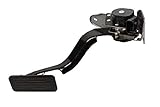
- The Accelerator Pedal Position sensor is part of the Accelerator Pedal Assembly (more specifically, it's bolted to the Accelerator Pedal Assembly).
- The accelerator pedal IS NOT connected to the throttle plate with an accelerator cable (like in the good ole' days).
- That the Accelerator Pedal Assembly is made up of 3 individual position sensors.
- Each one has separate signal, Ground, and 5.0 volt reference circuits.
- That APP Sensor 1's signal increases as the accelerator pedal is depressed, from below 1.1 volt at 0% pedal travel (pedal at rest) to above 2.1 Volts at 100% pedal travel (pedal fully depressed).
- That APP Sensor 2's signal decreases from above 3.9 Volts at 0% pedal travel to below 2.9 Volts at 100% pedal travel.
- That APP Sensor 3 's signal decreases from above 3.2 Volts at 0% pedal travel to below 3.1 Volts at 100% pedal travel (if applicable, since your specific vehicle may not use APP Sensor 3).
Contents of this tutorial:
- Symptoms Of A Bad APP Sensor 2.
- What Tools Do I Need?
- Where To Buy The APP Sensor.
- Circuit Descriptions Of The APP Sensor Assembly Connector.
- TEST 1: Resistance Test Of APP Sensor 2.
- TEST 2: 5 Volt Reference Circuit Test.
- TEST 3: Reference Low (Ground) Circuit Test.
- TEST 4: Testing The APP Sensor 2 Signal Circuit.
- Some Final Thoughts On APP Sensor 2.
Before we jump head-long into the info in this tutorial, let me tell you that there are several other tutorials which may be of help to you (which are also found here at easyautodiagnostics.com):
APP Sensor
- How To Test The GM Accelerator Pedal Position (APP) Sensor 1.
- Multimeter Resistance Specs of APP Sensor 1, APP Sensor 2.
TPS Sensor
- GM Electronic Throttle Body Circuit Descriptions And Testing Tips.
- Cleaning The GM Electronic Throttle Body (4.8L, 5.3L, 6.0L).
- P0120 TP Sensor 1 Circuit Malfunction (With Electronic Throttle Body).
- P0220 TP Sensor 2 Circuit Malfunction (With Electronic Throttle Body).
- Resistance Specifications Of The TAC Electronic Throttle Body.
![]() You can find this tutorial in Spanish here: Sensor 2 De La Posición Del Pedal Del Acelerador (GM 5.3L, 6.0L) (at: autotecnico-online.com).
You can find this tutorial in Spanish here: Sensor 2 De La Posición Del Pedal Del Acelerador (GM 5.3L, 6.0L) (at: autotecnico-online.com).
Symptoms Of A Bad APP Sensor 2
When the Accelerator Pedal Position (APP) Sensor 2 goes bad, you're gonna' see the following symptoms:
- Check engine light (CEL) will be lit on your instrument cluster.
- Diagnostic trouble code:
- P1125: Accelerator Pedal Position (APP) System.
- Lack of power when accelerating the engine.
- You'll see the message center display: 'Reduced Engine Power' (and of course the engine will operate in Reduced Engine Power mode).
- The engine may be turning off (this is done/determined by the PCM).
What Tools Do I Need?
The most important tool that you're gonna' need is a multimeter. Your multimeter can either be a digital multimeter (with a bar graph) or an analog multimeter.
Here are some of my suggestions:
- Analog multimeter or a digital multimeter with a bar graph.
- Your digital multimeter must have a bar graph to accurately test APP Sensor 2 in Ohms mode.
- The Fluke 115 digital multimeter has a bar graph. To see it, check out this article: Buying A Digital Multimeter For Automotive Diagnostic Testing.
- You can use an analog multimeter too.
- Generic scan tool.
- You don't need to use a generic scan tool to take advantage of the test info in this tutorial, since a generic scan tool can not dynamically test the APP sensor, but it does come in handy to read any trouble codes.
- If you don't own a scan tool yet, I recommend taking a look at these 2 articles I've written: Scan Tool Essentials You Should Know! (at: troubleshootmyvehicle.com) and Actron CP9580 Scan Tool Review (also at: troubleshootmyvehicle.com).
- Basic Hand Tools
- These are: ratchet wrench, sockets, etc., that you'll need to remove and replace the Accelerator Pedal Position (APP) Assembly.
Where To Buy The APP Sensor
You can buy the APP Sensor just about anywhere since all national (and local) auto parts stores carry them (AutoZone, O'Reilly Auto Parts, etc.).
But if you need to save some bucks, check out the link on the right. The link is for buying the APP Sensor only and not the entire pedal assembly (with sensor).
In case you didn't know, you don't have to buy the whole pedal assembly with the sensor attached if you don't have to.


Disclosure: As an Amazon Associate, I earn from qualifying purchases. Buying through these links helps support this site at no extra cost to you. Thanks for your support —it really means a lot!
Not sure if the accelerator pedal assembly or the APP sensor fits your particular vehicle? Don't worry. Once you get to the site they'll ask you for the particulars of your vehicle and they'll check it fits. If it doesn't fit, they'll find you the right one.
Circuit Descriptions Of The APP Sensor Assembly Connector
 Sensor, Pin Out Descriptions.")
Depending on whether your specific vehicle uses all 3 APP Sensor's or not, the APP Sensor Assembly's electrical connector could have 6 or 9 wires sticking out of it (whether the APP Sensor Assembly has 6 or 9 wires sticking out of its connector or not, this tutorial applies to them both).
The three wires (circuits) that feed Power, Ground and return a position signal (to APP Sensor 2) are:
- Circuit B, which is usually a Purple wire (ground).
- Circuit C, which is usually a Light Blue wire (APP Sensor 2 Signal).
- Circuit D, which is usually Tan wire (Power).
Below, you're gonna' find a table (chart) with the job description of each of the wires that stick out of the Electronic Throttle Body's electrical connector.
NOTE: There's a good chance that the colors of the wires described below may not match what's on your specific vehicle AND this is no cause for concern since the circuits are the same regardless of the color of the wire.
| APP Sensor Assembly Connector Pin outs | ||
|---|---|---|
| Pin | Wire Color | Description |
| A | Gray | APP Sensor 3 -Ground |
| B | Purple | APP Sensor 2 -Ground |
| C | Light Blue | APP Sensor 2 -Signal |
| D | Tan | APP Sensor 2 -5 Volt Reference Circuit |
| E | Yellow w/ Black stripe (or Brown) | APP Sensor 1 -Reference Low (Ground) Circuit |
| F | Dark Blue | APP Sensor 1 -Signal |
| G | White w/ Black stripe | APP Sensor 1 -5 Volt Reference Circuit |
| J | Brown (or Yellow w/ Black stripe) | APP Sensor 1 -Ground |
| K | Dark Green | APP Sensor 3 -Signal |
Let's turn the page and let's get testing.
TEST 1: Resistance Test Of APP Sensor 2
The very first test we're gonna' do, is to resistance test APP Sensor 2 with a multimeter. The circuits that you'll need to test (on the APP Sensor Assembly itself) are: C and D.
The APP Sensor 2 resistance test involves physically actuating the pedal down and up as you read the Ohms values on your analog multimeter (or digital multimeter with a bar graph).
The absolute best way to this is by removing the Pedal Assembly from the vehicle and bench-testing this resistance. Now, you don't have to remove the APP Sensor Assembly to test it, but it'll make the test a whole easier since you'll be able to easily attach your multimeter leads to the indicated APP Sensor Assembly pins with alligator clips (you can buy these at Radio Shack).
OK, this is what you need to do:
- Disconnect the battery negative (-) terminal.
- Disconnect the 6 (or 9) wire connector from the APP Sensor Assembly.
- Remove the APP Sensor Assembly by removing the bolts that attach it to the vehicle.
- Set your multimeter's dial on Ohm's mode (Ω) and locate metal pins C and D. Once you've identified them:
- Connect the red multimeter lead to pin C (this is the APP Sensor 2 Signal circuit).
- Connect the black multimeter lead to pin D (this is the APP Sensor 2 5 Volt power circuit).
- If all is OK up until this point, your multimeter should register about: 1.35 K Ω.
- TIP: To attach the multimeter lead to the pins and then actuate the pedal, you're gonna' need to use alligator clips (you can buy these at your local Radio Shack or electronics store).
- Now, manually depress and release the pedal (slowly) while you eye-ball your multimeter.
- When the pedal is fully depressed, your multimeter should register about 3.00 to 3.30 K Ω.
- Repeat the process several times, taking note of the sweep of the needle (analog multimeter) or sweep of the bar graph (digital multimeter with bar graph).
- If all is OK, the needle (or bar graph) will move up and down very smoothly (fluidly) without gaps or jerky movements.
Let's analyze your test results:
CASE 1: The multimeter's needle (or bar graph) moved up/down very smoothly. This tells you that APP Sensor 2 is OK.
The next step is to make sure that APP sensor is getting power (5 Volts) and Ground. Go to: TEST 2: 5 Volt Reference Circuit Test.
CASE 2: The multimeter's needle (or bar graph) DID NOT move up/down very smoothly. This tells you that APP Sensor 2 is bad.
To be more specific, the test result that indicates a problem with APP Sensor 2 is when the needle (or bar graph) on your multimeter does not swing smoothly. For example, as you're smoothly and slowly pushing the pedal down, your multimeter's needle hangs (stops abruptly) and moves up in a very jerky way AND this also happens as you slowly release the pedal too.