'Fly-by-wire' systems are being used in a lot of cars and pickups on the road today and one of the most common 'Fly-by-Wire' systems in use is the one that graces most of the newer GM pickups: the Electronic Throttle Body.
Everything you read about these systems indicate that they are the best thing to ever happen to automobiles. One of the statements that really makes me laugh is this one: 'The ETC delivers outstanding throttle response and greater reliability than a mechanical connection'.
The problems I've had with a throttle cable are so few and so far inbetween that I don't recall when was the last time I replaced one. When was the last time you replaced a throttle cable?
OK, enough of my ranting, in this article, I'll focus on the circuits of the Electronic Throttle Body and how to perform some basic tests on it. You may also be interested in the following tutorials:
- P0120 TP Sensor 1 Circuit Malfunction (With Electronic Throttle Body).
- P0220 TP Sensor 2 Circuit Malfunction (With Electronic Throttle Body).
Contents of this tutorial:
- Circuit Descriptions Of The GM Electronic Throttle Body.
- How Does The GM Electronic Throttle Body Work?
- Symptoms Of Electronic Throttle Control System Troubles.
- Electronic Throttle Body Connector Problems.
- Deposits Blocking The Throttle Plate.
- Testing The PCM's Grounds Basics.
- TEST 1: Voltage Drop Testing The PCM Grounds.
- How Does The Voltage Drop Test Work?
- TEST 2: Passlock Reset.
- Related Articles.
![]() You can find this tutorial in Spanish here: Lo Esencial del Cuerpo del Acelerador Electrónico (GM 5.3L, 6.0L) (at: autotecnico-online.com).
You can find this tutorial in Spanish here: Lo Esencial del Cuerpo del Acelerador Electrónico (GM 5.3L, 6.0L) (at: autotecnico-online.com).
Circuit Descriptions Of The GM Electronic Throttle Body

There are three major components of the GM Electronic Throttle Body and they are:
- Throttle body.
- Throttle Actuator Control (TAC) module.
- And Accelerator Pedal Assembly.
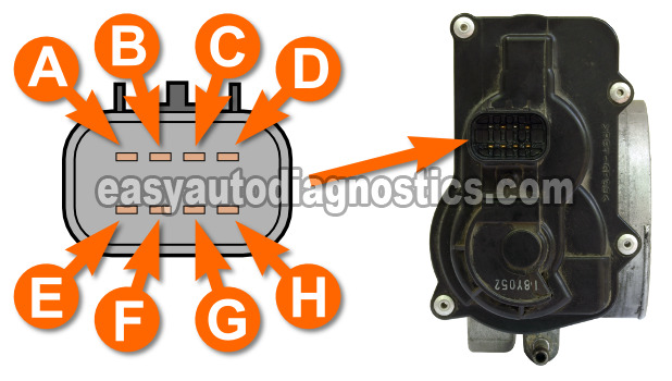
In this section, we'll focus on the Electronic Throttle Body. As you have probably already observed, there are 8 wires sticking out of the Electronic Throttle Body.
When looking down at the Electronic Throttle Body's connector, the top row (from left to right) has 4 wires which are labeled from A to D (see photo).
The second row (bottom row) from left to right, the wires are labeled E to H (see photo).
and here are their specific descriptions:
- A: (Yellow wire) TAC Motor Control -1.
- B: (Black with White stripe wire) Low Reference (Sensor Ground).
- C: (Brown wire) TAC Motor Control -2.
- D: (Black) Low Reference (Sensor Ground).
- E: (Light Blue with Black wire) 5 Volt Reference.
- F: (Purple) TP Sensor 2 Signal.
- G: (Dark Green) TP Sensor 1 Signal.
- H: (Grey) 5 Volt Reference.
Let's find out how the throttle body works in this system in the next subheading.
How Does The GM Electronic Throttle Body Work?

The Throttle Actuator Control (TAC) Module is the brain behind the Electronic Throttle Control System in the GM 4.8L, 5.3L, and 6.0L engines covered by this article.
The TAC Module is not part of the internal workings of the PCM and is usually located on the driver side of the firewall.
Inside the actual metal throttle body assembly, you'll find these important electrical components:
- 2 Throttle Position Sensors (TPS). These two are usually referred to as potentiometers, in the majority of the service literature.
- Throttle Actuator Control (TAC) Motor.
The one thing that hasn't changed is that a metal throttle plate is still needed to allow more or less air into the engine.
What has changed is the method used to open and close the throttle plate. In the good ole' days, an accelerator cable (that was mechanically attached to both the throttle and the accelerator pedal) was what controlled the amount of throttle plate angle.
In the Electronic Throttle Body setup, an electric motor (called the Throttle Actuator Control Motor) is the one that opens and closes the throttle valve.
To go into a bit more detail: when you step on or step off the accelerator pedal, the Throttle Actuator Control (TAC) Module translates the exact amount into a signal that opens the throttle plate. Here are some more specifics:
- The Throttle Actuator Control (TAC) Module receives input from the accelerator pedal position sensors in the accelerator pedal Assembly (inside the pickup or SUV).
- The potentiometers in the Accelerator Pedal Assembly are what tell the TAC Module how much you want to accelerate the engine.
- To open the throttle plate circuit A gets 12 Volts DC and circuit C becomes the Ground path.
- To close the throttle plate circuit A becomes the Ground path and circuit C becomes the power source.
- The voltage provided to the Throttle Actuator Control (TAC) Motor is a Pulse Width Modulated (PWM) Signal, which means that the TAC Module provides this voltage as a high frequency On/Off signal.
- The lower the voltage frequency, the slower the throttle plate opens (till it reaches WOT or the position commanded by your foot stepping on the accelerator pedal Assembly).
- The higher the voltage frequency, the faster the throttle plate opens (till it reaches WOT or the position commanded by your foot stepping on the accelerator pedal Assembly).
- The two throttle position sensors inside the Throttle Body Assembly report the change in Throttle Angle.
- Each TP Sensor gets 5 Volts.
- Each one also gets a Ground.
- Each one produces its own Throttle Angle signal.
- Both TP sensor signal voltages are low at closed throttle and increase as the throttle opens.
