
The blower motor control module is one of those components that, sooner or later, is going to fail on your Chevrolet Silverado or GMC Sierra pickup (equipped with automatic AC-Heater controls).
Instead of using old-school resistors to control blower motor speed, the blower control module electronically controls the blower motor by pulse-width modulating its Ground circuit.
From personal experience, I can tell you that testing the blower control module and finding out whether it's good or bad is pretty easy and can be done with a simple multimeter.
In this tutorial, I'll show you how to test it step by step.
Contents of this tutorial:
- Bad Blower Control Module Symptoms.
- Blower Motor Control Module Basics.
- Where To Buy The Blower Control Module And Save.
- IMPORTANT: Test The Blower Motor Before Replacing The Blower Control Module.
- TEST 1: Making Sure The Blower Control Module Is Getting 12 Volts.
- TEST 2: Making Sure The Blower Control Module Is Getting Ground.
- TEST 3: Checking The Blower Speed Signal.
- TEST 4: Checking Voltage Output To Blower Motor.
- TEST 5: Checking Ground Output To Blower Motor.
- More Silverado, Sierra, Suburban, Tahoe, And Yukon Tutorials.
APPLIES TO: This tutorial applies to the Chevrolet and GMC vehicles listed below.
View the complete vehicle application list
- Chevrolet Avalanche 1500: 2002, 2003, 2004, 2005, 2006.
- Chevrolet Avalanche 2500: 2002, 2003, 2004, 2005.
- Chevrolet Silverado 1500: 1999, 2000, 2001, 2002, 2003, 2004, 2005, 2006, 2007.
- Chevrolet Silverado 2500: 1999, 2000, 2001, 2002, 2003, 2004.
- Chevrolet Silverado 2500 HD: 2001, 2002, 2003, 2004, 2005, 2006.
- Chevrolet Silverado 3500 HD: 2001, 2002, 2003, 2004, 2005, 2006.
- Chevrolet Suburban 1500: 2000, 2001, 2002, 2003, 2004, 2005.
- Chevrolet Suburban 2500: 2000, 2001, 2002, 2003, 2004, 2005.
- Chevrolet Tahoe 2500: 2000, 2001, 2002, 2003, 2004, 2005.
- GMC Sierra 1500: 1999, 2000, 2001, 2002, 2003, 2004, 2005, 2006, 2007.
- GMC Sierra 2500: 1999, 2000, 2001, 2002, 2003, 2004.
- GMC Sierra 2500 HD: 2001, 2002, 2003, 2004, 2005, 2006.
- GMC Yukon: 2000, 2001, 2002, 2003, 2004, 2005.
- GMC Yukon XL 1500: 2000, 2001, 2002, 2003, 2004, 2005.
- GMC Yukon XL 2500: 2000, 2001, 2002, 2003, 2004, 2005.
Bad Blower Control Module Symptoms
When the blower control module fails, the most common symptom is that the blower motor stops working completely. In other words, you'll get no airflow from the vents, regardless of which blower speed you select.
Depending on how the module fails, however, you may experience one or more of the following symptoms:
- No blower motor operation at any speed: This is by far the most common symptom.
- Blower motor speed changes on its own.
- Blower motor runs at only one speed.
- Blower motor continues running after the ignition is turned OFF.
- This usually due to an internal short inside the blower control module, which can keep the blower motor running even after the key has been removed.
- Burning plastic smell or signs of overheating.
- A failed blower control module or an overheated electrical connector may produce a burning plastic odor. This is a very common problem.
Blower Motor Control Module Basics
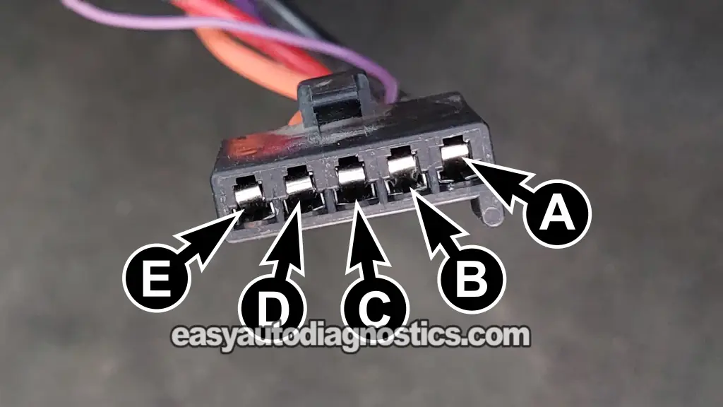
The blower motor control module is the component that controls blower motor speed on vehicles equipped with automatic A/C-heater controls. Instead of using fixed resistors to create the different blower speeds, it electronically controls the Ground circuit of the blower motor using pulse-width modulation (PWM). This allows the blower motor to operate at virtually any speed between low and high.
If your vehicle has manual A/C-heater controls, it does not use a blower motor control module. Instead, it uses a blower motor resistor assembly. The resistor assembly creates the different blower speeds by routing current through one or more resistors, while the highest blower speed usually bypasses the resistors altogether.
An easy way to tell the two systems apart is by looking at the electrical connectors. The manual A/C-heater blower resistor assembly uses a 7-terminal electrical connector plus the blower motor's 2-wire connector. The automatic A/C-heater blower control module, covered in this tutorial, uses a 5-terminal electrical connector (see the photo above).
In my experience, blower control module failures usually fall into one of two categories:
- The blower control module simply fails internally due to age and normal use.
- The blower motor wears out and begins drawing excessive current. Even though the blower motor may still run, the extra amperage overloads and overheats the blower control module and eventually damages it.
Where To Buy The Blower Control Module And Save

Disclosure: As an Amazon Associate, I earn from qualifying purchases. Buying through these links helps support this site at no extra cost to you. Thanks for your support —it really means a lot!
IMPORTANT: Test The Blower Motor Before Replacing The Blower Control Module
Before condemning the blower control module, make sure to test the blower motor's current (amperage) draw.
A blower motor that simply spins when battery power and Ground are applied isn't necessarily a good blower motor. As blower motors wear, their bearings begin to drag and the motor starts drawing more current than normal. Even though it still runs, the excessive current places an additional load on the blower control module.
Since the blower control module controls blower speed by pulse-width modulating the Ground circuit with a transistor, it normally generates a lot of heat during its operation. That's why it's mounted in the HVAC air stream, where the moving air helps keep it cool.
When the blower motor draws excessive current, the blower control module must dissipate even more heat. Over time, this extra heat can damage the module's internal electronic components and eventually cause it to fail.
For this reason, always check the blower motor before replacing the blower control module:
- Listen for excessive blower motor noise. If the blower motor is unusually loud or making a grinding noise while it's running, its bearings are probably worn and causing excessive drag. This will cause the blower motor to draw more current than normal.
- Check that the blower wheel spins freely. Remove the blower motor and spin the plastic blower wheel by hand. It should spin freely and smoothly. If it's difficult to turn or has excessive resistance, the blower motor has too much internal drag and will draw more current than normal.
- Check the blower motor's current draw. Even if the blower motor sounds normal and the blower wheel spins freely, test its amperage draw to make sure it isn't drawing excessive current.
If testing confirms that the blower control module has failed because the blower motor is drawing excessive current, replace both the blower motor and the blower control module. Replacing only the module without correcting the high current draw will cause the replacement module to fail prematurely.
TEST 1: Making Sure The Blower Control Module Is Getting 12 Volts
OK, to get our diagnostic started, the first thing that we're going to do is make sure that the blower control module is getting battery power.
This battery power (10 to 12 volts) are delivered to the blower control module by the red (RED) wire, which connects to terminal C of its 5-wire electrical connector.
This 12 Volt circuit is protected by a dedicated blower motor fuse. Since the fuse's location and amperage rating vary by vehicle, consult your owner's manual or a repair manual for your specific Chevrolet or GMC pickup.
One last thing. This battery power is available to the connector at all times, regardless of the ignition key position. To check for its presence at female terminal C of the connector, we're going to do a simple multimeter voltage test with a multimeter.
This is what you need to do:
- 1
Disconnect the blower motor control module from its 5-wire electrical connector.
- 2
Set your multimeter to Volts DC.
- 3
Connect the multimeter's black test lead directly to the battery negative (-) terminal or to a known good Ground point on the engine.
I like to use a battery jump start cable to connect my multimeter test lead directly to the battery negative (-) terminal. - 4
Probe terminal C with the multimeter's red test lead
Terminal C should connect to the RED wire of the 5-wire connector. - 5
Your multimeter should register battery voltage (approximately 12 Volts).
Let's interpret your multimeter test result:
CASE 1: The multimeter registered battery voltage (approximately 10 to 12 Volts). This test result confirms that the blower control module is receiving its battery power supply.
The next step is to make sure the blower control module has a good Ground. Go to: TEST 2: Making Sure The Blower Control Module Is Getting Ground.
CASE 2: The multimeter DID NOT register battery voltage. This test result tells you that the blower control module isn't receiving battery power. Without this power feed, the module cannot operate the blower motor.
The most likely causes are:
- An blown blower motor fuse.
- An open or damaged power wire between the fuse block and the blower control module.
Consult your owner's manual or a repair manual to identify the correct blower motor fuse for your specific Chevrolet or GMC pickup. If the fuse is OK, troubleshoot the power circuit between the fuse block and the blower control module.
Once battery power is restored to the blower control module, it should function again.
TEST 2: Making Sure The Blower Control Module Is Getting Ground
Now that we've confirmed that the blower control module is getting battery power, our next step is to make sure that it's getting Ground.
This Ground is a chassis Ground, and it's delivered to the blower motor control module connector by the black (BLK) wire that connects to terminal A of the connector.
Since this is a chassis Ground, it's available at all times, regardless of the ignition key's position.
We'll verify the Ground circuit by performing a simple voltage test with a multimeter. If the Ground circuit is working correctly, the multimeter will register battery voltage (10 to 12 Volts).
Let's get going:
- 1
Disconnect the blower motor control module from its 5-wire electrical connector.
- 2
Set your multimeter to Volts DC.
- 3
Connect the multimeter's red test lead directly to the battery positive (+) terminal.
I like to use a battery jump start cable to connect my multimeter test lead directly to the battery positive (+) terminal. - 4
Probe terminal A with the multimeter's black test lead
Terminal A should connect to the BLK wire of the 5-wire connector. - 5
Your multimeter should register 10 to 12 Volts DC.
Let's interpret your multimeter test result:
CASE 1: The multimeter registered battery voltage (approximately 10 to 12 Volts). This test result confirms that the blower control module has a good connection to Chassis Ground.
The next step is to verify that the blower control module is receiving the blower speed control signal from the A/C-heater control panel. Go to: TEST 3: Checking The Blower Speed Signal.
CASE 2: The multimeter DID NOT register battery voltage. This test result tells you that the blower control module is missing its Ground connection. Without a good Ground, the blower control module cannot operate the blower motor.
The most likely causes are:
- An open in the Ground wire between the blower control module and its chassis Ground connection.
- A poor or corroded chassis Ground connection.
Your next step is to troubleshoot this missing Ground and restore it to the circuit. Once the blower control module is getting chassis Ground, it should function again.
TEST 3: Checking The Blower Speed Signal
Now that we've confirmed the blower control module has both power and Ground, the next step is to verify that it's receiving the blower speed control signal from the A/C-heater control panel.
This blower speed signal is carried by the thin purple wire, which connects to terminal B of the blower control module's 5-wire electrical connector.
The way it technically works is that the blower motor control module supplies a reference voltage to the AC heater control panel. As you change the blower speed setting, the control panel lowers that voltage to command different blower speeds. In other words, the lower the voltage on the thin purple wire, the higher the commanded blower speed.
The way we're going to test it, we're not going to be using the reference voltage from the blower control module. Instead, we're going to connect our multimeter to battery power and then check to see if the AC heater control panel is modulating the Ground.
Don't worry, it's a pretty simple test, and it'll let you know if the AC heater control panel is actually sending a speed signal to the blower control module.
NOTE: The blower control module must remain connected to its 5-wire connector to accomplish this test. You'll need to back-probe the connector or use a wire-piercing probe on the wire. Don't have either tool, this is the one I use and recommend: Goupchn 4mm Banana to Banana Plug Test Leads Kit (Amazon affiliate link).
Alright, let's get started:
- 1
Reconnect the blower control module to its 5-wire connector.
- 2
Set your multimeter to Volts DC.
- 3
Connect the multimeter's red test lead to the battery positive (+) terminal.
- 4
Back-probe the thin purple wire (terminal B) with the multimeter's black test lead using an appropriate wire-piercing probe or by back-probing the connector.
- 5
Turn the ignition key to the ON position.
- 6
Move the blower speed selector through all of its speed settings and observe the multimeter. The voltage reading should change as the blower speed setting changes. These are the approximate voltage values you'll see:
Low Speed: Voltage fluctuates between 11.3 and 11.7 Volts DC.
Medium Speed: Voltage fluctuates between 8.7 and 9.9 Volts.
High Speed (Full Blast): Voltage fluctuates between 2.2 and 3.5 Volts DC.
Let's interpret your multimeter test result:
CASE 1: The voltage changed as the blower speed setting was changed. This test result confirms that the blower control module is receiving the blower speed command signal from the A/C-heater control panel.
The next step is to verify that the blower control module is supplying power to the blower motor. Go to: TEST 4: Checking Voltage Output To Blower Motor.
CASE 2: The voltage did not change or no voltage was present. This test result indicates that the blower control module isn't receiving a valid blower speed command signal.
The most likely causes are:
- A faulty A/C-heater control panel.
- An open or shorted blower speed signal wire between the A/C-heater control panel and the blower control module.
- A poor electrical connection at either connector.
Your next step is to troubleshoot the cause of the missing blower speed signal and restore it to the circuit.
TEST 4: Checking Voltage Output To Blower Motor
In this test, we're going to make sure the blower control module is supplying battery voltage to the blower motor.
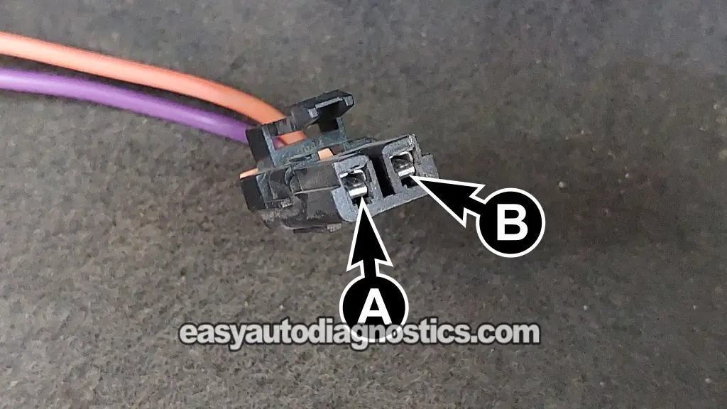
To do this test, the blower control module must remain connected to its 5-wire electrical connector. You'll disconnect the blower motor's 2-wire electrical connector and check for voltage on the purple (PPL) of the connector (that plugs into the blower motor).
The PPL wire connects to the female terminal I've labeled with the letter A in the image above.
OK, these are the test steps:
- 1
Reconnect the blower control module to its 5-wire connector if it's unplugged from it.
- 2
Disconnect the 2-wire electrical connector from the blower motor.
- 3
Turn the ignition key to the ON position and place the blower speed selector in any speed setting (LOW, MEDIUM, or HIGH).
- 4
Set your multimeter to Volts DC.
- 5
Connect the multimeter's black test lead to the battery negative (-) terminal or to a known good Ground.
- 6
Probe the terminal of the blower motor connector that connects to the purple (PPL) wire with the multimeter's red test lead.
- 7
Your multimeter should register approximately 10 to 12 Volts DC.
Let's interpret your multimeter test result:
CASE 1: The multimeter registered approximately 10 to 12 Volts DC. This test result confirms that the blower control module is supplying battery voltage to the blower motor.
The next step is to verify that the blower control module is supplying the Ground path to the blower motor. Go to: TEST 5: Checking Ground Output To Blower Motor.
CASE 2: The multimeter DID NOT register 10 to 12 Volts DC. If you've already confirmed in the previous tests that the blower control module:
- Is receiving battery voltage (TEST 1).
- Has a good Ground (TEST 2).
- Is receiving the blower speed control signal from the A/C-heater control panel (TEST 3).
Then the blower motor control module has failed internally and needs to be replaced.
TEST 5: Checking Ground Output To Blower Motor
The last test is to make sure the blower control module is providing the Ground path for the blower motor.
Unlike a conventional Ground circuit, the blower control module doesn't simply switch Ground ON and OFF. Instead, it controls blower motor speed by pulse-width modulating (PWM) the Ground circuit. As you change the blower speed, the module changes the PWM duty cycle of the Ground circuit accordingly.
In a nutshell:
- The higher the blower speed selected, the greater the PWM duty cycle applied to the Ground circuit.
- The lower the blower speed selected, the lower the PWM duty cycle applied to the Ground circuit.
In layman's terms, this means:
- At HIGH blower speed, the module keeps the Ground connected most of the time.
- At LOW blower speed, the module connects the Ground for much less time.
We'll verify that the blower control module is producing this PWM Ground signal by measuring the voltage on the orange (ORG) wire of the blower motor connector (terminal B of the blower motor's 2-wire connector). As the blower speed changes, the measured voltage should change accordingly.
Let's get going:
- 1
Make sure the blower control module is connected to its 5-wire connector.
- 2
Disconnect the blower motor from its 2-wire connector.
- 3
Set your multimeter to Volts DC.
- 4
Connect the multimeter's red test lead to the battery positive (+) terminal.
- 5
Probe terminal B of the blower motor connector and keep the probe making continuous contact.
Terminal B should connect to the orange (ORG) wire with the multimeter's black test lead.
NOTE: On some vehicles, this wire will be a black (BLK) wire instead of ORG. - 6
Turn the ignition key to the ON position.
- 7
Place the blower speed selector on HIGH and note the voltage reading.
You should see approximately 10 to 12 Volts (close to battery voltage). - 8
Move the blower speed selector to LOW and note the new voltage reading.
The voltage should drop significantly (typically around 2 to 4 Volts). This indicates the blower control module is pulse-width modulating the Ground circuit to reduce blower motor speed.
Let's interpret your multimeter test result:
CASE 1: The voltage changed as the blower speed was changed as indicated. This test result confirms that the blower control module is pulse-width modulating the Ground circuit correctly. If all five tests have produced the expected results, then the blower control module is functioning correctly.
If the blower motor still doesn't operate properly, the problem is most likely caused by the blower motor itself or by excessive mechanical restriction in the HVAC system, such as severely clogged cabin air filters.
CASE 2: The voltage did not change as the blower speed was changed, or there was no Ground output. If you've already confirmed that the blower control module:
- Is receiving battery voltage (TEST 1).
- Has a good Ground (TEST 2).
- Is receiving the blower speed control signal from the A/C-heater control panel (TEST 3).
- Is supplying battery voltage to the blower motor (TEST 4).
Then the blower control module has failed internally and needs to be replaced.
More Silverado, Sierra, Suburban, Tahoe, And Yukon Tutorials
You can find a complete list of V8 Chevrolet Silverado (Sierra, Suburban, Tahoe) and GMC Sierra (Yukon, Yukon XL) tutorials in this index:
Here's a small sample of the tutorials you'll find in the index:
- Resistance Specifications Of The TAC Electronic Throttle Body.
- How To Test The GM Accelerator Pedal Position (APP) Sensor 2.
- How To Test The MAF Sensor (GM 4.8L, 5.3L, 6.0L, 8.1L).
- Blown Head Gasket Test (GM 4.8L, 5.3L, 6.0L).

If this info saved the day, buy me a beer!
