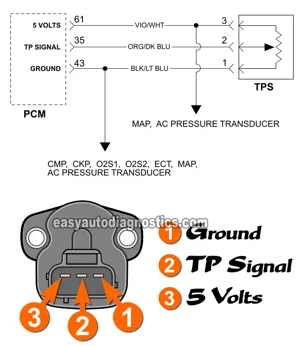
Circuit Diagram Of The Throttle Position Sensor (TPS)

NOTE: The illustration of the TPS circuit diagram applies only to the following Dodge Plymouth minivans:
- 1998, 1999, 2000 3.0L Dodge Caravan.
- 1998, 1999, 2000 3.0L Grand Caravan.
- 1998, 1999, 2000 3.0L Plymouth Voyager.
- 1998, 1999, 2000 3.0L Plymouth Grand Voyager.
TPS PIN #1: Ground input to the TPS. This wire is a black with light blue stripe (BLK/LT BLU) color. It connects directly to PCM connector terminal number 43.
The BLK/LT BLU wire also feeds Ground to the following sensors:
- CMP -Camshaft Position Sensor.
- CKP -Crankshaft Position Sensor.
- O2S1 -Front Oxygen Sensor (before catalytic converter).
- O2S2 -Rear Oxygen Sensor (after catalytic converter).
- ECT -Engine Coolant Temperature Sensor.
- MAP -Manifold Absolute Pressure Sensor.
- AC PRESSURE TRANSDUCER -AC High Pressure Switch.
TPS PIN #2: TP signal output to the PCM. This wire is a orange with dark blue stripe (ORG/DK BLU) wire. It connects directly to the Powertrain Control Module (PCM) connector terminal number 35.
TPS PIN #3: 5 Volts DC input to the throttle position sensor (TPS). This wire is a violet with white stripe (VIO/WHT) color. It connects directly to the Powertrain Control Module (PCM) connector terminal number 61.
The VIO/WHT wire also feeds 5 Volts to the following sensors:
- MAP sensor.
- AC Pressure Transducer.
More 3.0L Chrysler Diagnostic Tutorials
You can find a complete list of 3.0L Chrysler/Dodge/Plymouth tutorials in this index:
Here's a small sample of the tutorials you'll find in the index:
- How To Test For A Broken Timing Belt (1988-2000 3.0L SOHC Chrysler) (at troubleshootmyvehicle.com).
- How To Replace The Distributor (1988-2000 3.0L Chrysler) (at troubleshootmyvehicle.com).
- How To Test The Throttle Position Sensor (1991-1995 3.0L Chrysler) (at troubleshootmyvehicle.com).

If this info saved the day, buy me a beer!


