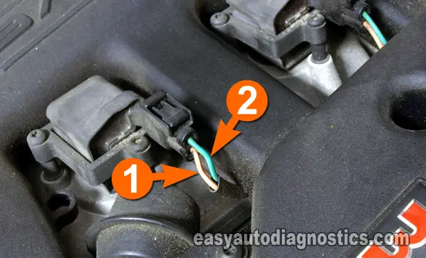
TEST 2: Testing The Power Circuit (12 Volts)

All six ignition coils are fed power (12 Volts) from the same circuit. You can use a multimeter or a 12 Volt test light to verify this voltage.
The instruction below assume that you'll be using a multimeter to verify the presence of 12 Volts in the circuit.
IMPORTANT: If you decide to test the front of the terminal for 12 Volts, be careful not to damage it.
OK, here's the test:
- 1
Disconnect the ignition coil from its electrical connector.
- 2
Put the multimeter in Volts DC mode.
- 3
Connect the black multimeter test lead to the battery negative (-) terminal.
- 4
With the red multimeter test lead, probe the female terminal that connects to the wire labeled with the number 2.
- 5
Have your helper crank the engine
NOTE: Power is only available when cranking the engine. - 6
You should see 10-12 Volts on your multimeter.
Let's take a look at what your test results mean:
CASE 1: The multimeter registered 10-12 Volts (or the test light lit up). This is the correct test result and you can conclude that the power circuit is OK and is delivering voltage. The next step is to test the Ground circuit, go to: TEST 3: Testing The Switching Signal.
CASE 2: The multimeter DID NOT register 10-12 Volts (or the test light DID NOT light up). Then the power circuit has a problem. This result eliminates the COP ignition coil as the source of the misfire condition. The power circuit is shared by all of the COP ignition coils.
TEST 3: Testing The Switching Signal

The Switching Signal is the one that activates the ignition coil to fire off spark. This signal comes from the PCM (Powertrain Control Module=Fuel Injection Computer), since Chrysler (Dodge and Plymouth) vehicles do not use an externally mounted ignition control module to activate the ignition coils.
This signal can be verified very easily using an LED Light. One more thing, since this signal comes directly from the computer, be careful not to short this circuit to battery 12 Volts or you'll fry the computer.
NOTE: There are two ways to check that the non-sparking ignition coil is receiving its activation signal. The second method is here: TEST 4: Testing The Trigger Signal (2nd Method).
These are the test steps:
- 1
Disconnect the ignition coil from its electrical connector.
- 2
Connect the black lead of the LED light to the female terminal of the connector that connects to the wire labeled with the number 1 in the photo.
NOTE: Be careful not to damage the female terminal of the connector when inserting the end of the LED light, or you'll damage the terminal and you'll need to replace the connector. - 3
Connect the red lead of the LED Light to the female terminal of the connector that connects to the wire labeled with the number 2 in the photo.
NOTE: Be careful not to damage the female terminal of the connector when inserting the end of the LED light, or you'll damage the terminal and you'll need to replace the connector. - 4
When all is ready, have your helper crank the engine
NOTE: Be careful, the engine may start. - 5
The LED Light should blink ON and OFF the whole time the engine is cranking and running.
Let's take a look at what your test results mean:
CASE 1: The LED Light blinked ON and OFF. This is the correct test result and confirms that the PCM is feeding the Switching Signal to the ignition coil.
This test result also indicates that the ignition coil is bad. Replace the ignition coil.
CASE 2: The LED Light DID NOT blink ON and OFF. Then this result indicates that the PCM is NOT feeding the Switching Signal to the ignition coil. This also indicates that the ignition coil is bad. Replace the ignition coil.
This lack of Signal indicates one of two things: 1) An open-circuit problem in the circuit between the COP ignition coil and the PCM or 2) a bad PCM, altho' a bad PCM is rare, but it happens.
