TEST 1: Testing The Power (12 V) Circuit
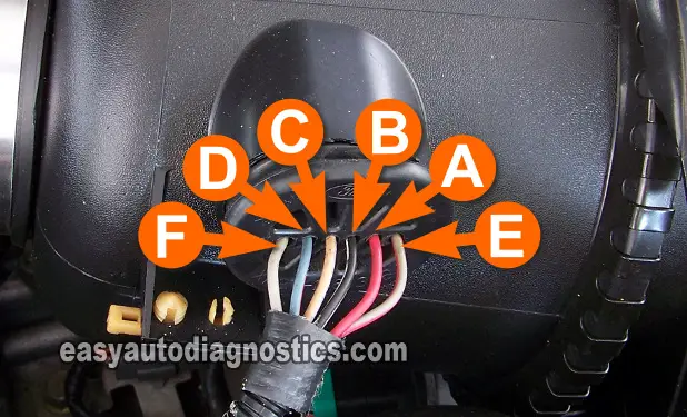
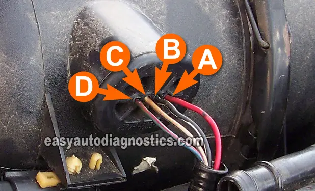
For all of the tests, you'll need to use the photos in the image viewers to identify the circuit (wire) that the Test indicates you need to test.
The very first thing that we'll do is check that the MAF sensor is receiving a healthy supply of 12 Volts.
As mentioned before, use a test probe that pierces thru' the wire's insulation (Wire Piercing Probe) to get to the signal inside the wire.
Also, don't disconnect the round air filter canister assembly from the air duct that connects it to the intake manifold's throttle body.
Alright, these are the test steps:
- 1
Place your multimeter in Volts DC mode.
Don't have a digital multimeter? Need to buy one? Click here to see my recommendations: Buying A Digital Multimeter For Automotive Diagnostic Testing. - 2
With the red multimeter test lead and an appropriate tool, probe the MAF sensor connector's circuit labeled with the letter A (see photos above).
- 3
Connect the black multimeter test lead to the battery negative (-) terminal.
- 4
Turn key ON but don't crank or start the engine.
- 5
Your multimeter should register 10 to 12 Volts.
Let's take a look at what your test result means:
CASE 1: The multimeter registered 10 to 12 Volts. This is the correct test result and tells you that the power circuit is OK.
The next step is to make sure that the MAF sensor is getting Ground. For this test go to: TEST 2: Testing The Ground Circuit.
CASE 2: The multimeter DID NOT register 10 to 12 Volts. This tells you that the MAP sensor is not getting power.
This test result also tells you that the MAF sensor is not the problem. Without juice (12 Volts) in this circuit, the Mass Air Flow (MAF) sensor won't work.
Your next step is to find out why this power was missing and restore it.
TEST 2: Testing The Ground Circuit
Now that you've confirmed that the MAF sensor is getting 10 to 12 Volts, the next step is to make sure it's getting chassis Ground.
This Ground circuit ends at the battery negative (-) terminal and in this test step, you'll make sure that it's present by doing a simple multimeter voltage test.
The wire that feeds this chassis Ground to the MAF sensor is the wire labeled with the letter B in the photos in the image viewer.
This is what you'll do:
- 1
Turn key to the OFF Position.
- 2
Place the multimeter in Volts DC mode.
- 3
Connect the black multimeter test lead (with a wire-piercing-probe), to the circuit identified with the letter B in the photo.
- 4
Connect red lead to the battery positive (+) terminal.
- 5
Your multimeter should read 10 to 12 Volts DC.
NOTE: No need to turn the key to the ON position, since the multimeter should automatically read battery voltage as soon as the connection is made.
Let's take a look at what your test result means:
CASE 1: The multimeter registered 10 to 12 Volts. This test result tells you that the MAF sensor is getting Ground.
The next step is now to make sure that the MAF sensor is getting Ground from the fuel injection computer. This Ground is called the Sensor Return Ground. For this test go to: TEST 3: Testing The 2nd Ground Circuit.
CASE 2: The multimeter DID NOT register 10 to 12 Volts. This test result confirms that the MAF sensor is not getting the chassis Ground it needs to function.
You can also conclude that the MAF sensor is not the problem. Without a clear path to Ground in this wire, the MAF sensor will not work. The next step is to find out why this Ground is missing and restore it


