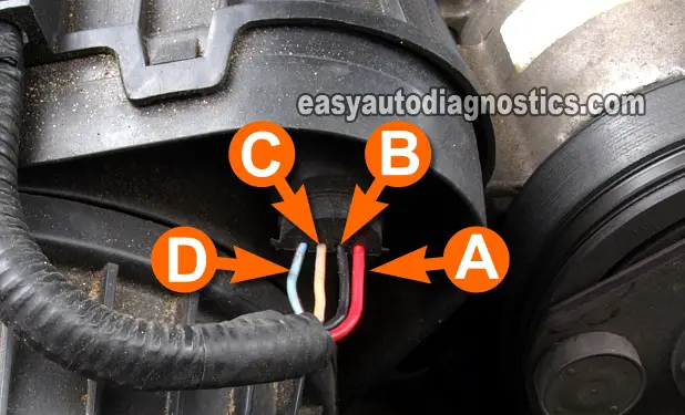
TEST 2: Testing The Power (12 V) Circuit

For our second test, we'll check that the MAF sensor is receiving a healthy supply of 10 to 12 Volts DC.
These 10 to 12 Volts are provided by the wire labeled with the letter A in the photo above.
- 1
Place your multimeter in Volts DC mode.
- 2
With the red multimeter test lead and an appropriate tool, probe the MAF sensor connector's circuit labeled with the letter A, as shown in the photo.
- 3
Connect the black multimeter test lead on the battery negative (-) terminal.
- 4
Turn key ON with the engine OFF.
- 5
Your multimeter should register 10 to 12 Volts.
Let's take a look at what your test results mean:
CASE 1: The multimeter registered 10 to 12 Volts. This tells you that the MAP sensor is getting power.
Now we need to make sure that the MAF sensor is getting Ground. For this test go to: TEST 3: Testing The Chassis Ground Circuit.
CASE 2: The multimeter DID NOT register 10 to 12 Volts. This test result tells you that the MAF sensor isn't being fed with power.
This test result also tells you that the MAF sensor itself is not the problem since without power the MAF sensor will not work.
Although it's beyond the scope of this tutorial, your next step is to find out why this voltage is missing and restore it. Once the MAF sensor is getting 12 Volts, it'll function again.
TEST 3: Testing The Chassis Ground Circuit

Now that you've confirmed that the MAF sensor is getting power we're gonna' check that it's getting chassis Ground.
This chassis Ground wire, the one labeled with the number B (in the photo above), goes directly to the battery negative (-) terminal.
Here's how to test it:
- 1
Turn key to the OFF Position.
- 2
Place your multimeter in Volts DC mode.
- 3
Connect the black multimeter test lead to the wire identified with the letter B in the photo above.
- 4
Connect red multimeter test lead to the battery positive (+) terminal.
- 5
Your multimeter should read 10 to 12 Volts DC.
No need to turn the key to the ON position, since the multimeter should automatically read battery voltage as soon as the connection is made.
Let's find out what your test result means:
CASE 1: The multimeter registered 10 to 12 Volts. This tells you that the MAP sensor is getting chassis Ground.
Now we need to make sure that the MAF sensor is getting Ground from the PCM on the wire labeled with the letter C. For this test go to: TEST 4: Testing The 2nd Ground Circuit.
CASE 2: The multimeter DID NOT register 10 to 12 Volts. This test result tells you that the MAF sensor isn't being fed with chassis Ground.
This test result also tells you that the MAF sensor itself is not the problem since without this Ground the MAF sensor will not work.
Although it's beyond the scope of this tutorial, your next step is to find out why this Ground is missing and restore it. Once the MAF sensor is getting chassis Ground, it'll function again.
TEST 4: Testing The 2nd Ground Circuit

The second Ground (called the Sensor Return Ground) is provided internally by your Mustang's PCM.
This Sensor Return Ground is provided to the MAF sensor by the wire identified with the letter C (in the photo above.)
NOTE: Because the PCM is the one that provides this path to Ground, you have to be careful and not short this wire (circuit) to battery power (12 Volts), or you'll fry the PCM. Again, be careful. The multimeter test I'm suggesting in the test instructions is a safe way to test for the presence of Ground in this wire.
These are the test steps:
- 1
Turn key to the OFF Position.
- 2
Place the multimeter in Volts DC mode.
- 3
With the black multimeter test lead and an appropriate tool, probe the MAF sensor connector's circuit identified with the letter C as shown in the photo.
- 4
Connect the red multimeter test lead to the battery positive (+) terminal.
- 5
Turn the ignition switch to the RUN position (no need to crank or start the engine).
- 6
The multimeter should register battery voltage (10 to 12 Volts).
Let's take a look at what your test result means:
CASE 1: The multimeter registered 10 to 12 Volts. This tells you that this Ground circuit is OK.
You can conclude that the MAF sensor is bad if you have:
- Confirmed that the MAF sensor is not producing a voltage signal that increases/decreases as you accelerate/decelerate the engine (TEST 1).
- Confirmed that the MAF sensor is getting 10 to 12 Volts (TEST 2).
- Confirmed that the MAF sensor is getting chassis Ground (TEST 3).
- Confirmed that the MAF sensor is getting Ground from the PCM (this test section).
CASE 2: The multimeter DID NOT register 10 to 12 Volts. This test result lets you know the MAF sensor itself isn't the problem. Without the PCM providing this Ground, the MAF sensor will not work.
Your next step is to find out why this PCM Ground is missing and restore it. Once the MAF sensor is getting Ground from the PCM again, it'll function.

If this info saved the day, buy me a beer!

