TEST 2: Testing The Ground Circuit

Here we'll check that the Chevy Cavalier or Pontiac Sunfire's ignition control module is receiving a good GROUND.
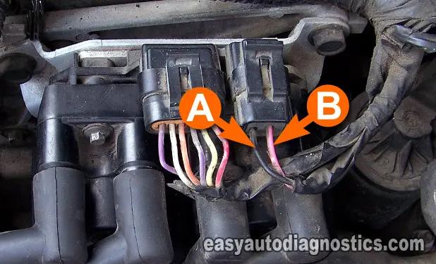
Ground is fed to the ignition control module thru' the A circuit of the connector with 2 wires.
Let's get started:
- 1
Put the multimeter in Volts DC mode.
- 2
Disconnect the ignition control module (ICM) from its 2-wire electrical connector.
- 3
Connect the red multimeter test lead to the battery positive (+) terminal.
- 4
Probe the black (BLK) wire of the connector with the black multimeter test lead.
In the photo above, this wire is labeled with the letter A.
NOTE: This wire will either be a black wire or a black with white stripe wire. - 5
You should see 10 to 12 Volts on the multimeter.
Let's take a look at what your test results mean:
CASE 1: The multimeter registered the indicated voltage. All is good in the neighborhood, go to: TEST 3: Testing The CKP Sensor Signal.
CASE 2: The multimeter DID NOT register the indicated voltage. This means there is open in this circuit. The ignition module needs this GROUND to function. Repair this problem before continuing.
TEST 3: Testing The CKP Sensor Signal
Now we're gonna' test the signal from crankshaft position sensor. This will be achieved by using a multimeter (or an oscilloscope).
You're gonna' probe both wires at the same time to get an AC voltage reading.
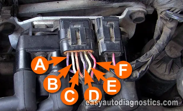
The two wires are the A (purple) and E (yellow) wires of the 6-wire connector (see photo above).
IMPORTANT: The battery must be in a fully charged condition for this test.
CAUTION: You'll be working around a cranking engine. Be careful, use common sense and take all necessary safety precautions.
These are the test steps:
- 1
Disconnect the ignition control module from its 6-wire electrical connector.
- 2
Put the multimeter in AC Volts mode..
- 3
Connect the multimeter test leads to either of the two wires with suitable tools (the polarity of the multimeter's test leads don't matter on this test).
- 4
With the key ON and engine NOT CRANKING, you should have 0 Volts AC.
- 5
Have an assistant crank the engine while you observe the multimeter (or oscilloscope).
- 6
The multimeter's AC reading should fluctuate from 0.5 V AC to 1.3 V AC continuously as the engine is cranking.
The minimum and maximum AC voltage reading attained will depend on the cranking RPMs. Engine temperature, oil viscosity and battery charge condition will have a direct effect on this.
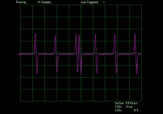
If you're using an oscilloscope, look at image 2 for the wave form
Let's interpret your test result:
CASE 1: The multimeter registered the indicated voltage. Good, this means that the CKP sensor is working properly, go to: TEST 4: Testing The 7X REFERENCE Signal.
CASE 2: The multimeter DID NOT register the indicated voltage. If you have no AC voltage, recheck all connections. Try again. If you still have no AC voltage, the CKP sensor is defective. Replace the sensor.


