TEST 4: Ignition Coil Switching Signal Circuit

OK, if you read the basic theory section, at the beginning of the tutorial, you know that the switching signal activates the ignition coil to start sparking away.
In this test section you'll test for the presence of this signal using an LED Light. Do not use a 12 Volt test light for this test.
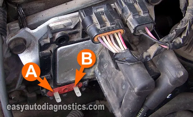
NOTE: Although the photo above only shows the ignition coil pack that feeds spark to cylinders 1 and 4 removed, the following test steps also apply to the ignition coil pack that feeds spark to cylinders 2 and 3.
These are the test steps:
- 1
Connect the black lead of the LED light to the male spade terminal labeled with the letter B in the photo above.
- 2
Connect the red lead of the LED light to the positive (+) battery terminal.
- 3
When all is ready, have your assistant crank the engine while you observe the LED Light.
- 4
The LED light should blink ON and OFF the whole time the engine is cranking.
Let's take a look at what your test results mean:
CASE 1: The LED light blinked ON and OFF while the engine was cranking. This result confirms the ignition coil pack is bad. Replace the ignition coil pack.
Here's why: If the ignition coil is receiving power, which you verified in TEST 3, and is getting the switching signal from the ignition control module (ICM), then it has to spark. Since it isn't, you now know beyond a shadow of a doubt it's bad.
CASE 2: The LED light DID NOT blink ON and OFF while the engine was cranking. This test result confirms that the ignition control module (ICM) is bad.
Replacing the ignition control module will solve the no-spark condition on these two 'paired cylinders' that aren't getting spark.
TEST 5: Ignition Module's Triggering Signal

If in TEST 1 all the plug wires did not spark, there is a good chance that:
- The ignition control module (ICM) isn't getting the Triggering signals it needs to activate the ignition coil packs.
- The ignition control module is bad.
In this test step, I'll show you how to test for these two IC Signal (Ignition Control Signals).
To accomplish this test, you'll need a multimeter that can read Hertz (Hz) frequency. Don't have a digital multimeter that can read Hertz frequency? See my recommendations here: Buying A Digital Multimeter For Automotive Diagnostic Testing
PART 1:
- 1
Place the multimeter in frequency Hz mode.
- 2
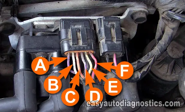
Connect the red multimeter test lead to the wire labeled with the letter B.
This the Triggering signal (IC Signal) wire for the coil pack feeding spark to cylinders 1 and 4.
NOTE: Both ignition control module connectors MUST be connected to the ignition control module (ICM). - 3
Connect the black multimeter test lead to the battery negative (-) terminal or a good Ground on the engine.
- 4
With the key ON and engine NOT CRANKING, you should have 0 Hz.
- 5
Have an assistant crank the engine while you observe the multimeter (or oscilloscope).
- 6
The multimeter should register a Hertz reading fluctuating around 3 Hz as the engine is cranking.
NOTE: The minimum and maximum Hertz reading attained will depend on the cranking RPMs. Engine temperature, oil viscosity and battery charge condition will have a direct effect on this.
PART 2:
- 7
Disconnect the red multimeter test lead from the wire that you just tested.
- 8
Connect the red multimeter test lead to the wire labeled with the letter C.
This the Triggering signal (IC Signal) wire for the coil pack feeding spark to cylinders 2 and 3. - 9
Connect the black multimeter test lead to the battery negative (-) terminal.
- 10
Turn the Key ON, but don't crank the engine.
- 11
You should have 0 Hz.
- 12
Have your assistant crank the engine while you observe the multimeter (or oscilloscope).
- 13
The multimeter should register a Hertz reading fluctuating around 3 Hz as the engine is cranking.
Let's take a look at what your test results mean:
CASE 1: The multimeter registered the indicated Hertz (Hz) values on both circuits. This is the correct and expected test result.
You can conclude the ignition control module is bad and needs to be replaced (to solve your 'no-spark no-start' condition) if you have:
- Confirmed all spark plug wires ARE NOT sparking (TEST 1).
CASE 2: The multimeter DID NOT register the indicated Hertz (Hz) values on both circuits. This test result usually indicates the crankshaft position sensor is bad.
Although testing the crankshaft position (CKP) sensor is beyond the scope of this tutorial, you can find the CKP sensor test here:
