TEST 5: 1-4 & 2-3 Coil Control Signal

After the ECM receives the 7X Reference signal, it sends the ignition control module (ICM) two signals.
One is the 1-4 Coil Control Signal and the other is the 2-3 Coil Control Signal. These are the input signals that the ignition control module needs and uses to start sparking the two ignition coils (that are connected to it).
In this test step, we're gonna' test these two signals (individually) with a multimeter that can read Hertz (Hz) Frequency (or an oscilloscope).
You can test either of the wires first. The specification of the signal reading (on the multimeter or oscilloscope) will be the same for both circuits, since the signals are identical to each other.
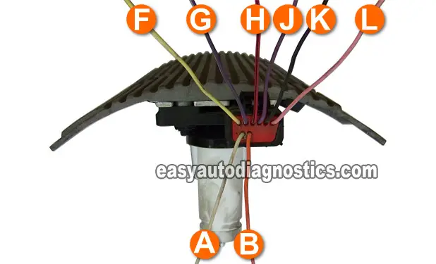
You'll be testing the A circuit (WHITE wire) and B circuit (ORANGE wire) of the ICM's harness connector.
IMPORTANT: To ensure the most accurate test result, the battery must be in a fully charged condition for this test. Also, you'll be working around a cranking engine; be careful, use common sense and take all necessary safety precautions
- 1
Put multimeter in frequency Hz mode (don't have a digital multimeter that can read Hertz frequency? See my recommendations here: Buying A Digital Multimeter For Automotive Diagnostic Testing).
- 2
The ignition module connector MUST be connected to the ignition control module.
- 3
Connect the red test lead of the multimeter to the either wire.
- 4
Connect the black test lead of the multimeter to engine Ground.
- 5
With the key ON and engine NOT CRANKING, you should have 0 Hz.
- 6
Have an assistant crank the engine while you observe the multimeter (or oscilloscope).
- 7
The multimeter's Hertz reading should fluctuate around 5 Hz as the engine is cranking (the minimum and maximum Hertz reading attained will depend on the cranking RPMs. Engine temperature, oil viscosity and battery charge condition will have a direct effect on this).
- 8
Now test the other circuit (you should see similar readings).
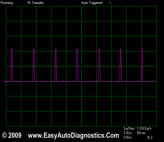
Did the multimeter show the above Hertz readings? (Oscilloscope users see image below for full size picture of wave form)
CASE 1: Your multimeter registered the indicated Hertz values. This means that the ignition control module is defective. Replace it.
Here's why: So far you have:
- Confirmed that the ICM is getting power (TEST 1).
- Confirmed that the ICM is getting Ground (TEST 2).
- Confirmed that the crankshaft position sensor is creating/feeding a signal to the ICM (TEST 3).
- Confirmed that the ICM is creating a 7X Reference signal (the ECM needs to start activating the fuel injectors, etc) (TEST 4).
- In this test, you have confirmed that the ICM is getting both Ignition Control Signals from the ECM.
Taking all of the above into account, the ignition control module is receiving all of the signals (inputs) it needs to activate the ignition coils, since it isn't, we can conclude the ignition control module is bad and needs to be replaced.
NOTE: Remember, this test result interpretation only applies if at the beginning of your diagnostic you confirmed that there's NO SPARK present at any of the coil towers (as mentioned in the beginning of this tutorial on page 1).
CASE 2: Your multimeter DID NOT register the indicated Hertz values. Recheck all connections and repeat the test.
If your multimeter still does not register any Hertz numbers, then this test result tells you that the ignition control module is not the cause of the NO-SPARK NO-START CONDITION, since without these 2 signals it can't activate the ignition coils.
Although it's beyond the scope of this tutorial, you'll need to find out why these 2 Ignition Coil Control Signals are missing.

TEST 6: Crankshaft Position Sensor Resistance

Before I go any further, I want to thank Nick (who owns 95 Grand Am with a Quad 4) for suggesting this important test. So Nick, thanks for making the time to share your diagnostic experience!
OK, the test in this section involves testing the resistance of the crankshaft position sensor with your multimeter in Ohm mode.
You'll be able to accomplish this test right from the ignition module's connector and this is what you need to do:
- 1
Disconnect the ignition module's connector.
- 2
Probe the two wires labeled with the letters F and J. These two are the ones that connect directly to the crankshaft position sensor.
NOTE: You can probe the front of the connector if you like with the multimeter leads, but be very careful you don't permanently open up the metal terminals. - 3
The resistance value your multimeter should register should be between 500 to 900 Ohms (Ω).
Let's take a look at what your test results mean:
CASE 1: Your multimeter registered the indicated Ohms values. This means that the crankshaft position sensor is OK. The next step is to see if the module is now converting the crank signal into the 7X Reference signal. Go to: TEST 4: Testing The 7X Reference Signal..
CASE 2: Your multimeter DID NOT register the indicated Ohms values. This means that the crankshaft position sensor is bad.
Although in TEST 3 your multimeter indicated that the crankshaft position sensor produced the indicated AC voltage crankshaft position signal, this test confirms that the crankshaft position sensor is bad. Replace the crankshaft position sensor.
Reader's Real Life Case Studies And Solutions
In this section, is input and feedback from all of the folks who have had a similar issue with their vehicle and found a solution. If you're one of them, thank you for sharing your experience with all of us! If you want to share your repair and/or diagnostic experience, you can use the contact form below.
Real Life Case Study 1
Vehicle: 1995 Pontiac Grand Am 2.3L
Trouble Codes: None
Complaint: No-Start No-Spark Condition.
Repair: ' Thanks so much for this writeup. The oscilloscope pictures were especially helpful. I thought I might suggest adding a step about measuring the resistance across the CKP sensor terminals. I was able to get a waveform from the CKP sensor similar to that pictured, but I wasn't getting the 7X reference signal. It turned out that the CKP sensor had become a virtual open (2.4MOhms). My service manual suggests that the resistance should be around 800 Ohms. The replacement sensor I purchased tested around this value and sure enough fixed the problem. Knowing to test the CKP sensor resistance might have saved me from trying a replacement ICM first. ”
Courtesy of: Nick Bertrand

If this info saved the day, buy me a beer!

