TEST 2: Making Sure The Blower Switch Is Getting Power

In this second test section, we're gonna make sure that the blower speed switch is getting power.
This power is in the form of battery voltage, which should be in the range of 10 to 12 Volts DC.
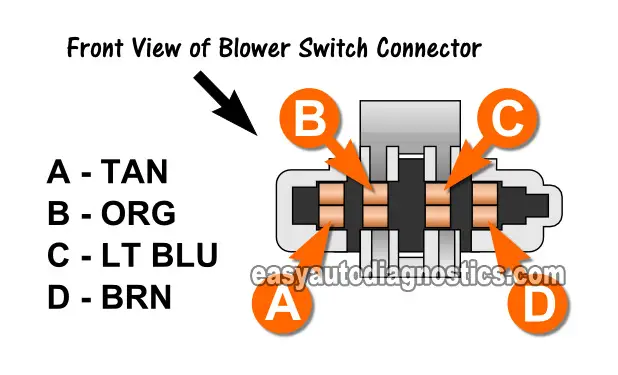
These 10 to 12 Volts are fed to the blower speed switch by the brown (BRN) wire of the blower speed switch's connector.
The BRN wire is the one that connects to the connector terminal labeled with the letter D in the illustration above.
Let's get testing:
- 1
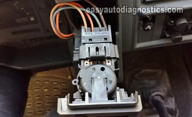
Disconnect the blower motor switch from its connector.
- 2
Place your multimeter in Volts DC mode.
- 3
Turn the AC/Heater Control Panel lever to any position but OFF.
By this I mean place the lever in any of the following positions: MAX AC, NORM AC, BI-LEV AC, VENT, or HTR. - 4
Turn the key to the RUN position but don't crank or start the engine.
- 5
With the red multimeter test lead, probe the D terminal of the blower switch connector.
- 6
Ground the black multimeter test lead on a clean and rust free metal surface on your S10/S15.
I suggest using a jump start cable to Ground the black multimeter test lead to the battery negative (-) terminal (this will ensure a good Ground). - 7
Your multimeter should register 10 to 12 Volts DC if the blower switch is getting power.
Let's find out what your test results mean:
CASE 1: Power is available at terminal D. This is the correct and expected test result and tells you that the blower speed switch is getting battery power.
Your next step is to use a jumper wire and bypass the blower speed switch. For this test, go to: TEST 3: Using a Jumper Wire To Bypass The Blower Speed Switch.
CASE 2: Power IS NOT available at terminal D. This usually means that the fuse that feeds this power is blown or missing.
The fuse that feeds this power to the blower motor switch is the HTR/AC fuse located in the fuse panel under the dash (on the driver's side). Check the fuse and retest.
TEST 3: Using A Jumper Wire To Bypass The Blower Switch

In this final test section, we'll use a jumper wire on the blower speed switch connector to bypass the switch and connect the blower speed circuits directly, instead of relying on the switch to do it.
Bypassing the blower speed switch will help accomplish two things:
- Indirectly test the blower speed switch.
- Check the circuits between the switch and the blower resistor assembly and blower motor relay.
IMPORTANT: Be careful not to damage the female terminals of the blower speed switch connector with your jumper wire. If the jumper wire terminal you insert into the female terminal is too thick, it can damage the terminal and result in an intermittent 'open-circuit' issue
Alright, these are the test steps:
- 1
Turn the ignition key to the OFF position.
- 2
Disconnect the blower motor switch from its harness connector.
NOTE: All tests in this section are done on the blower speed switch harness connector and not on the switch itself. The illustration above shows the front view of the female metal terminals of the blower speed switch connector. - 3
Place the AC/Heater Control Panel lever in any position but OFF (for example: MAX AC, NORM AC, BI-LEV AC, VENT, or HTR).
- 4
Turn the key to the RUN position.
The blower motor should run at LO speed without jumpering any of the terminals of the switch connector.
Turn the ignition key OFF once you've verified the blower motor ran (or did not run). - 5
Jumper terminals D and A together and turn the ignition key to the RUN position (but don't start the engine).
The blower motor should run at M1 speed with terminals D and A jumpered together.
Turn the ignition key OFF once you've verified the blower motor ran (or did not run). - 6
Jumper terminals D and C together and turn the ignition key to the RUN position (but don't start the engine).
The blower motor should run at M2 speed with terminals D and C jumpered together.
Turn the ignition key OFF once you've verified the blower motor ran (or did not run). - 7
Jumper terminals D and B together and turn the ignition key to the RUN position (but don't start the engine).
The blower motor should run at HI speed with terminals D and B jumpered together.
Turn the ignition key OFF once you've verified the blower motor ran (or did not run).
Let's examine your test results:
CASE 1: The blower motor ran when all of the indicated terminals were jumpered together. This tells you several important things:
- That the circuits between the blower motor resistor assembly connector and the blower motor are OK.
- That the blower motor relay is OK.
No further testing is required of the blower motor resistor assembly, the blower relay or the blower motor.
CASE 2: The blower motor DID NOT run when the HI circuit was jumpered but LO, M1, and M2 produced the indicated test result. This usually tells you that the blower motor relay is bad.
If the blower speed switch passed the HI circuit continuity test in TEST 1, you can confidently assume that the problem with HI speed IS NOT related to the blower speed switch.
The following tutorial will help you test the blower motor relay:
CASE 3: The blower motor DID NOT run when testing circuits LO, M1, and M2 but ran when the HI circuit was jumpered. This usually tells you that the blower motor resistor assembly is fried and needs to be replaced.
The blower motor resistor assembly can be tested to be sure it's good or bad. You can find the tutorial here:

More 2.8L Chevy S10 Pickup, GMC S15 Pickup, And GMC Sonoma Tutorials
You can find a complete list of tutorials for the 2.8L V6 Chevrolet S10 pickup, GMC S15 pickup, and GMC Sonoma in this index:
Here's a sample of the articles, you'll find in the Index of Articles:
- How To Test The Fuel Pump (1988-1993 2.8L Chevrolet S10 Pickup, GMC S15 Pickup, GMC Sonoma).
- How To Test Engine Compression (1988-1993 2.8L Chevrolet S10 Pickup, GMC S15 Pickup, GMC Sonoma).
- How To Test The EGR Valve (1988-1993 2.8L Chevrolet S10 Pickup, GMC S15 Pickup, GMC Sonoma).
- How To Test The Starter Motor (1988-1993 2.8L V6 Chevrolet S10 Pickup, GMC S15 Pickup).

If this info saved the day, buy me a beer!


