TEST 2: Testing The Power Circuit For 12 Volts

The first thing we need to do, to get this MAF sensor diagnostic underway, is to make sure it's getting power.
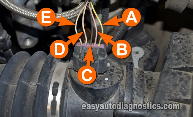
Power comes in the form of 12 Volts DC with the Key On Engine Off (and engine running of course) and is fed to the MAF sensor thru the pink wire (this is the wire labeled with the letter B in the photo above.
You can use a 12 Volt test light or a multimeter to test for power, although the test steps assume you're using a multimeter.
OK, this is what you'll need to do:
- 1
Place your multimeter's dial to Volts DC mode.
- 2
Connect the red multimeter test lead to the pink (PNK) wire identified with the letter B (see image above) using the appropriate tool.
- 3
Connect the black lead of the multimeter to a good Ground point on the engine or to the battery negative (-) terminal.
- 4
Turn the key to the ON position but don't crank or start the engine and observe the voltage value the multimeter registers.
- 5
The multimeter should register between 10 to 12 Volts DC.
Let's take a look at what your test results mean:
CASE 1: The multimeter registered 10 to 12 Volts DC. This is good and it's the correct test result. Now you know that the mass air flow (MAF) sensor is getting juice.
The next step is to verify that it's also getting a good Ground, go to: TEST 3: Testing The Ground Circuit.
CASE 2: The multimeter DID NOT register 10 to 12 Volts DC. This is not good. Recheck your multimeter connections and test again.
If you still don't see 10 to 12 Volts (on your multimeter), then this exonerates the MAF sensor as being bad, since without 12 Volts, the MAF sensor will not work. Repairing the cause of the missing voltage will solve the MAF problem.
TEST 3: Testing The Ground Circuit

Now that we know that the mass air flow (MAF) sensor is getting juice, the next step is to make sure it's getting Ground.
Ground is provided by the black with white stripe wire and is the wire labeled with the letter C in the photo above.
OK, you'll be using your multimeter (in Volts DC) to confirm this Ground is working.
This is what you need to do:
- 1
Place your multimeter in Volts DC mode.
- 2
Connect the black multimeter test lead to the black with white stripe (BLK/WHT) wire identified with the letter C using an appropriate tool.
- 3
Connect the red lead of the multimeter to the battery positive (+) terminal.
- 4
Turn the key to the ON position but don't crank or start the engine and observe the voltage value the multimeter registers.
- 5
The multimeter should register between 10 to 12 Volts DC.
Let's take a look at what your test results mean:
CASE 1: The multimeter registered 10 to 12 Volts DC. This test result indicates that the MAF sensor has a good Ground.
You can conclude that the MAF sensor is bad and needs to be replaced if you have:
- Confirmed that MAF signal output does not increase/decrease as you accelerate/decelerate the engine (TEST 1).
- Confirmed that the MAF sensor is getting 10 to 12 Volts DC (TEST 2).
- Confirmed that the MAF sensor is getting Ground (this test section).
CASE 2: The multimeter DID NOT register 10 to 12 Volts DC. Double check your multimeter connections and retest.
If your multimeter still does not show the indicated 10 to 12 Volts, then this exonerates the MAF sensor as being bad, since without a good Ground, the MAF sensor will not work and this will light up the check engine light (CEL) on your instrument cluster.
Although it's beyond the scope of this tutorial, but repairing the cause of the missing Ground will solve the mass air flow sensor problem.
Oscilloscope Waveform Of The GM MAF Sensor

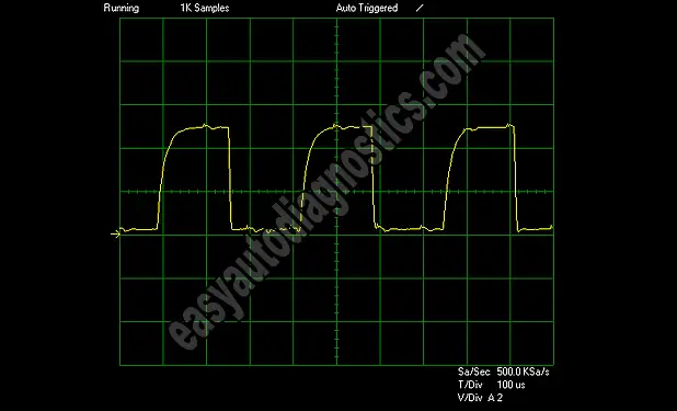
If you have access to an oscilloscope, this is what the mass air flow (MAF) sensor waveform looks like at idle.
If the MAF sensor is good then at idle and at any RPM, the waveform will stay perfectly formed. Also, as you accelerate the engine, the wave-length will become shorter while the wave amplitude stays the same.
Now, if the MAF sensor is bad, the waveform will have missing pieces or no waveform will be formed at all.

If this info saved the day, buy me a beer!

