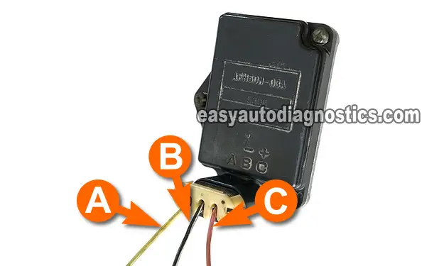
TEST 2: Testing The Power (12 V) Circuit

In this test section, we're gonna check if the MAF sensor is receiving 12 Volts.
The wire that provides this voltage to the MAF sensor is the wire labeled with the letter C in the photo above.
We'll perform a simple multimeter voltage test to see if the wire is delivering 10 to 12 Volts to the MAF sensor.
IMPORTANT: When probing the front of the connector's female terminals, be careful not to damage the terminal with the multimeter's test lead.
- 1
Put the multimeter in Volts DC mode.
- 2
Disconnect the MAF sensor from its connector.
- 3
With the red multimeter test lead and an appropriate tool, probe the female terminal of the connector that connects to the wire labeled with the letter C (see photo above).
- 4
Connect the black multimeter test lead on the battery negative (-) terminal.
- 5
Turn key ON with the engine OFF.
- 6
The multimeter should register 10 to 12 Volts DC.
Let's interpret your test result:
CASE 1: The multimeter registered 10 to 12 Volts. All is good in the neighborhood as this result confirms the MAF sensor is getting power.
The next and final test is to make sure the MAF sensor is getting Ground, go to: TEST 3: Testing The Ground Circuit.
CASE 2: The multimeter DID NOT register 10 to 12 Volts. The MAF sensor is not the problem. Without this voltage the MAF sensor will not work.
TEST 3: Testing The Ground Circuit

In the previous test we checked that the sensor is receiving 10 to 12 Volts. Now we'll check that the MAF sensor is getting a good Ground.
As you can see in the photo, this is the middle wire of the MAF sensor's connector, which I've labeled with the letter B.
We'll do a simple multimeter voltage test to check for the presence of Ground in this wire.
IMPORTANT: When probing the front of the connector's female terminals, be careful not to damage the terminal with the multimeter's test lead.
NOTE: The test steps assume you're using a multimeter with Hertz measurement capability. If you're using a
These are the test steps:
- 1
Put the multimeter in Volts DC mode.
- 2
Disconnect the MAF sensor from its connector.
- 3
With the black multimeter test lead and an appropriate tool, probe the female terminal of the connector that connects to the wire labeled with the letter B (see photo above).
- 4
Connect the red multimeter test lead on the battery positive (+) terminal.
- 5
The multimeter should register 10 to 12 Volts DC.
Let's examine your test result:
CASE 1: The multimeter registered 10 to 12 Volts. This is the correct test result and it confirms the MAF sensor is getting Ground.
You can conclude the MAF sensor is bad and needs to be replaced if you have:
- Confirmed that the MAF signal does not increase/decrease as you accelerate/decelerate the engine (TEST 1).
- Confirmed that the MAF sensor is getting 10 to 12 Volts (TEST 2).
- Confirmed that the MAF sensor is getting Ground (this test section).
CASE 2: The multimeter DID NOT register 10 to 12 Volts. The MAF sensor is not the problem. Without this path to Ground, the MAF sensor will not work.

If this info saved the day, buy me a beer!

