This tutorial will show you how to test the MAF on your GM car, pick up, or SUV using a digital multimeter and without using a scan tool.
All you need (to diagnose and troubleshoot the MAF sensor) is a digital multimeter capable of reading Hertz (Hz) frequency.
This type of GM mass air flow (MAF) sensor is used in a lot of GM makes and models, to find out if this article applies to your specific GM (Cadillac, Chevy, Buick, GMC) vehicle, take a look at the 'Applies To' list.
Contents of this tutorial:
- Symptoms Of A Bad GM MAF Sensor.
- What Tools Do I Need?
- Where To Buy The MAF Sensor And Save.
- Circuit Descriptions Of The MAF Sensor Connector.
- TEST 1: Testing The Power Circuit For 12 Volts.
- TEST 2: Testing The Ground Circuit.
- TEST 3: Testing The MAF Signal Circuit.
- Oscilloscope Waveform Of The GM MAF Sensor.
- More 4.8L, 5.3L, And 6.0L GM Tutorials.
![]() You can find this tutorial in Spanish here: Cómo Probar El Sensor MAF (GM 4.8L, 5.3L, 6.0L, 8.1L) (at: autotecnico-online.com).
You can find this tutorial in Spanish here: Cómo Probar El Sensor MAF (GM 4.8L, 5.3L, 6.0L, 8.1L) (at: autotecnico-online.com).
RELATED TROUBLE CODES:
Now, in case this is not the article you're looking for, there are also 3 other GM MAF sensor test articles:
- How To Test The GM Mass Air Flow Sensor: GMC Savana Van and Chevy Express Van 4.3L, 5.3L, 6.0L Engines (2003-2008)
- How To Test The GM Mass Air Flow Sensor (Early Type): Buick, Chevy, Olds, Pontiac 3.1L, 3.4L, 4.3L, 5.0L, 5.7L V6 Engines (1996-2005)
- How To Test The GM MAF Sensor: Buick, Chevy, Olds, Pontiac 3.8L V6 Engines (1996-2005)
- How To Test The MAF Sensor on 3.1L, 3.3L, and 3.8L Buick, Oldsmobile, Pontiac (1988-1996)
Symptoms Of A Bad GM MAF Sensor
The most obvious one is that the check engine light (CEL) will be on on your instrument cluster and driving you nuts. Here are a couple of others:
- A MAF sensor diagnostic trouble code (DTC) stored in your vehicle computer's memory.
- P0101: MAF Sensor System Performance Problem
- P0102: MAF Sensor Circuit Low Frequency
- P0103: MAF Sensor Circuit High Frequency
- Lean and/or Rich diagnostic trouble code(s).
- P0171, P0174
- Fuel Trim diagnostic trouble code(s).
- No power when you accelerate the car or truck.
- Black smoke coming from the tail-pipe.
- Your car or truck or SUV may idle rough and stall.
What Tools Do I Need?
You'll need a digital multimeter that can read Hertz (Hz) frequency, since the MAF sensor signal a Hz frequency output.
Now if you don't have a digital multimeter that can read Hertz frequency, check out my recommendations here: Buying A Digital Multimeter For Automotive Diagnostic Testing.
As mentioned earlier, you don't need an automotive scan tool to test the MAF sensor. Having said that, a scan tool is one of those MUST have tools to be able check and diagnose today's modern cars and trucks, but for the tests in this article you don't need one.
Where To Buy The MAF Sensor And Save
To avoid having the repair come back, you should avoid buying a cheap knock-off MAF sensor.
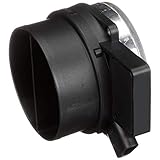
The following links will help you comparison shop for the original equipment (OE) Delphi and AC-Delco MAF sensor:
Disclosure: As an Amazon Associate, I earn from qualifying purchases. Buying through these links helps support this site at no extra cost to you. Thanks for your support —it really means a lot!
Circuit Descriptions Of The MAF Sensor Connector

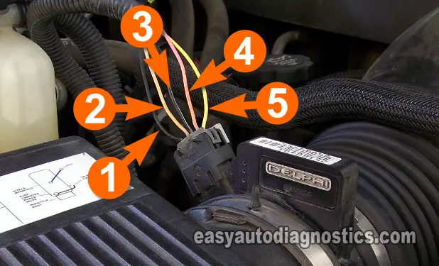
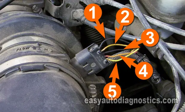
There are five wires coming out of the GM mass air flow (MAF) sensor. To be able to diagnose and troubleshoot this GM MAF sensor, you'll need to know what each one of those wires does and how to test the signal that is carried by it. Below are the circuit descriptions that you'll be using thru' out the article.
- Circuit labeled 1:
- Air Temperature Sensor Circuit
- Circuit labeled 2:
- Air Temperature Sensor Circuit
- Circuit labeled 3:
- Ground Circuit.
- Circuit labeled 4:
- Power (12 Volts) Circuit.
- Circuit labeled 5:
- MAF Signal Circuit.
I did not include the color of the wires because as long as you're able to identify them by the number in the photo, you'll be OK. Also, the color of the wires in the photos may not be the color of the wires of the MAF on your specific vehicle and again this is no cause for concern.
TEST 1: Testing The Power Circuit For 12 Volts

OK, the very first thing that you'll need to do is to make sure the mass air flow (MAF) sensor is getting power (12 Volts). You can use a test light or a multimeter. The following test steps assume that you're using a multimeter.
By the way, I recommend that you test the circuit with the connector connected to the mass air flow (MAF) sensor and using a wire piercing probe (or any other appropriate tool) to pierce the wire (to get to the signal). Probing the front of the terminal, to get to the 12 Volt Signal, could lead to some major complications.
OK, nuff said, here's the test:
- 1
Place the multimeter in Volts DC mode.
- 2
Disconnect the MAF sensor from its connector.
- 3
Connect the red multimeter test lead to the PINK wire identified with the number 4 (see photo above) using an appropriate tool.
- 4
Connect the black multimeter test lead to the battery negative (-) terminal.
- 5
Turn the key to the ON position and observe the voltage value the multimeter registers.
- 6
The multimeter should register between 10 to 12 Volts DC.
Let's take a look at what your test results mean:
CASE 1: The multimeter registered 10 to 12 Volts DC. This is the correct test result and it indicates that the MAF sensor is getting juice (12 Volts).
The next step is to verify that it's also getting a good Ground, go to: TEST 2: Testing The Ground Circuit.
CASE 2: The multimeter DID NOT register 10 to 12 Volts DC. Without power the MAF sensor will not work.
This test result exonerates the MAF sensor itself as being bad. Repairing the cause of the missing voltage will solve the MAF sensor problem.


