TEST 2: Testing The Ground Circuit

Testing the Ground circuit follows pretty much the same procedure as the test steps for testing the power circuit. Here are the steps:
- 1
Place the multimeter in Volts DC mode.
- 2
Disconnect the MAF sensor from its connector.
- 3
Connect the black multimeter test lead to the black (or black with white stripe) wire identified with the number 3, in the photo above, using an appropriate tool.
- 4
Connect the red multimeter test lead to the battery positive (+) terminal.
- 5
Turn the key to the ON position and observe the voltage value the multimeter registers.
- 6
The multimeter should register between 10 to 12 Volts DC.
Let's take a look at what your test results mean:
CASE 1: The multimeter registered 10 to 12 Volts DC. This is the correct test result and it indicates that the MAF sensor is getting Ground.
The next step is to verify that the MAF sensor is creating a good MAF Signal based on the airflow the engine is breathing, go to: TEST 3: Testing The MAF Signal Circuit.
CASE 2: The multimeter DID NOT register 10 to 12 Volts DC. Without Ground the MAF sensor will not function.
This test result exonerates the MAF sensor itself as being bad. Repairing the cause of the missing Ground will solve the problem.
TEST 3: Testing The MAF Signal Circuit

Before you jump into this last test, let's go over some basic working theory of how the mass air flow (MAF) sensor works that'll help you to breeze thru' it.
The MAF sensor's job is to measure the amount of air the engine is breathing at any given RPM and to convert this measurement into a Hertz frequency reading (as measured by a digital multimeter that can read Hz frequency) the PCM can use to calculate fuel injection.
Therefore the more air the engine breathes, the higher the Hertz frequency that the MAF sensor will output to the PCM.
So keeping this in mind, the Hertz frequency reading will be higher at 2500 RPM than at 800 RPM. On your multimeter, this Hertz (Hz) reading will increase as you accelerate the engine and decrease as the engine decelerates.
Now, if the MAF sensor is bad, you'll see the Hertz reading stuck in one value as you accelerate/decelerate the engine.
NOTE: Start the engine and let it reach its normal operating temperature before starting the test.
IMPORTANT: The MAF sensor must be connected to its connector to perform this test. You'll need to use a back probe on the connector or a wire piercing probe on the wire. You can see an example of this tool here: Wire Piercing Probe Review (Power Probe PWPPPPP01).
Let's get testing:
- 1
Connect the red multimeter test lead to the wire identified with the number 5 in the photo above.
- 2
Put the multimeter in Hertz frequency (Hz) mode.
If you don't have a digital multimeter that can read Hertz frequency? Check my recommendations here: Buying A Digital Multimeter For Automotive Diagnostic Testing. - 3
Connect the black multimeter test lead to the battery negative (-) terminal.
- 4
Start the already warmed up engine.
- 5
Note the Hertz reading on your multimeter at idle.
This reading may be stable (with only small fluctuations) or unstable with very extreme fluctuations. No matter what the instability in the reading, this will be your base reading. - 6
Manually accelerate the engine from the engine compartment as you watch the multimeter's frequency readings.
- 7
The Hertz frequency readings should increase as you open the throttle.
- 8
Slowly release close the throttle to let the engine return to idle.
- 9
The Hertz reading should decrease to the base Hertz reading you observed in step 5 of this test.
- 10
Accelerate and decelerate the engine several times as you observe the multimeter.
The multimeter Hertz reading should increase/decrease as you accelerate/decelerate the engine.
Let's take a look at what your test results mean:
CASE 1: The Hertz (Hz) signal increased and decreased as the engine was accelerated and decelerated respectively. This is the correct test result and it tells you that the mass air flow (MAF) sensor is working correctly.
CASE 2: The Hertz (Hz) signal DID NOT increase nor decreased as the engine was accelerated and decelerated respectively. This test result indicates that the MAF sensor is not producing a good MAF signal.
You can conclude that the MAF sensor is bad if you have:
- Confirmed that the MAF sensor is getting power (TEST 1).
- Confirmed that the MAF sensor is getting Ground (TEST 2).
- Confirmed that the MAF signal DOES NOT increase/decrease as you accelerate/decelerate the engine.
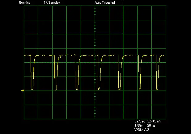
Oscilloscope Waveform Of The GM MAF Sensor

If you have access to an oscilloscope, this is what the mass air flow (MAF) sensor waveform looks like at idle.
If the MAF sensor is good then at idle and at any RPM, the waveform will stay perfectly formed. Also, as you accelerate the engine, the wave-length will become shorter while the wave amplitude stays the same.
Now, if the MAF sensor is bad, the waveform will have missing pieces or no waveform will be formed at all.
More 4.8L, 5.3L, And 6.0L GM Tutorials
You can find a complete list of V8 Chevrolet Silverado (GMC Sierra) tutorials in this index:
Here's a small sample of the tutorials you'll find in the index:
- Resistance Specifications Of The TAC Electronic Throttle Body.
- How To Test The GM Accelerator Pedal Position (APP) Sensor 2.
- How To Test The MAF Sensor (GM 4.8L, 5.3L, 6.0L, 8.1L).
- Blown Head Gasket Test (GM 4.8L, 5.3L, 6.0L).

If this info saved the day, buy me a beer!

