TEST 2: Testing For Spark Directly At The COP Coil

It's possible that the spark plug wire (high tension wire), that's attached to the COP ignition coil, is bad.
To prove this, you need to remove the spark plug wire from its COP ignition coil and test for spark directly on the COP coil tower.
This test will either eliminate or condemn the spark plug wire as good or bad.
These are the test steps:
- 1
Remove the spark plug wire that did not spark from the ignition coil.
- 2
Attach the HEI spark tester directly to the coil-On-Plug (COP) ignition coil's tower as shown in the photo above.
- 3
Connect the HEI spark tester to the battery negative (-) terminal using a battery jump start cable.
- 4
Have your helper crank the engine while you observe the spark tester.
- 5
You'll get one of two results:
1.) The spark tester will spark.
2.) The spark tester will NOT spark. - 6
Repeat the test for all of the remaining Coil-On-Plug ignition coils whose spark plug did not fire off spark in TEST 1 (if applicable).
Let's take a look at what your test results mean:
CASE 1: You got spark. This is the correct test result and it tells you that the COP ignition coil is good and the spark plug wire (high tension wire) is bad.
Replacing the spark plug wires (as a set) should solve the misfire condition or misfire code that's lighting up your check engine light (CEL) on your instrument cluster.
As a side note, if your GM (or Hummer or Isuzu Pick Up or Van or SUV) has over 100,000 miles, I recommend that you replace all of the spark plugs also (for preventive maintenance sake).
CASE 2: You got NO spark. The next step is to verify that this specific Coil-On-Plug ignition coil is receiving 12 Volts, Ground, and its Triggering signal from the PCM.
Go to: TEST 3: Testing The Power Circuit (12 Volts).
TEST 3: Testing The Power Circuit (12 Volts)

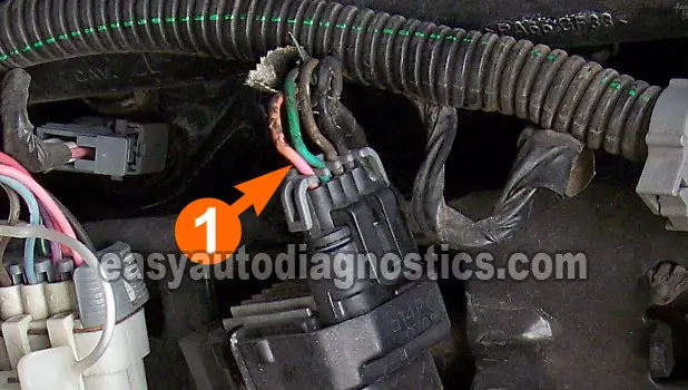
The ignition coil needs power, in the form of 10 to 12 Volts to function. In this test section, we'll check that they're available on the wire labeled with the number 1 in the photo above.
Testing for this voltage can easily be done with your multimeter in Volts DC.
Here's the test:
- 1
Disconnect the ignition coil connected to its connector.
- 2
Place your multimeter in Volts DC mode.
- 3
Probe the circuit labeled with the number 1 (in the photo above) with the red multimeter test lead.
You can either back probe the connector, or use a wire piercing probe on the wire.
If you probe the front of the connector, be careful not to damage the female terminal. - 4
Connect the black multimeter test lead probe the battery negative (-) terminal.
- 5
Have your helper turn the key to the ON position.
- 6
You should see 10 to 12 Volts on your multimeter.
Let's take a look at what your test results mean:
CASE 1: The multimeter registered 10 to 12 Volts (or the test light lit up). This is the correct test result and it lets you know that the power circuit is OK and is delivering voltage.
The next step is to test the Ground circuit, go to: TEST 4: Testing The Ground Circuit.
CASE 2: The multimeter DID NOT register 10 to 12 Volts (or the test light DID NOT light up). Then the power circuit has a problem.
This result eliminates the COP ignition coil as the source of the misfire condition. The power circuit is shared by all of the COP ignition coils.
Your next step is to find out why these 12 Volts are missing and repair the problem.
TEST 4: Testing The Ground Circuit

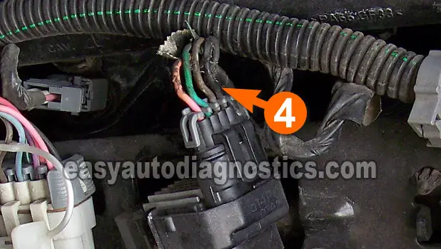
The ignition coil is fed 2 different Grounds. One is a chassis Ground (which will confirm in this test) and the other is a PCM Ground (supplied internally by the PCM).
The fastest and easiest way to check the ignition coil's chassis Ground is by doing a simple multimeter voltage test.
These are the test steps:
- 1
Disconnect the ignition coil from its connector.
- 2
Place your multimeter in Volts DC mode.
- 3
Probe the circuit labeled with the number 4 (in the photo above) with the black multimeter test lead.
You can either back probe the connector, or use a wire piercing probe on the wire.
If you probe the front of the connector, be careful not to damage the female terminal. - 4
Connect the red multimeter test lead probe the battery positive (+) terminal.
- 5
Have your helper turn the key to the ON position but don't crank or start the engine.
- 6
You should see 10 to 12 Volts on your multimeter.
Let's take a look at what your test results mean:
CASE 1: The multimeter registered 10 to 12 Volts (or the test light lit up). This is the correct test result and it confirms that the COP ignition coil is getting Ground.
The next step is to test the Ground circuit provided by the PCM, go to: TEST 5: Testing The Low Reference Circuit.
CASE 2: The multimeter DID NOT register 10 to 12 Volts (or the test light DID NOT light up). Then the chassis Ground circuit has a problem.
Recheck all of your multimeter connections and retest. If still the multimeter does NOT register the specified voltage, then this result eliminates the COP ignition coil as the source of the misfire condition. You must find out the cause of this open-circuit problem in the wire.
