A Digital Signal For A Digital Age
OK, so far you've also learned that the two wire type (also known as a magnetic pulse generator type sensor, among several names) produces an analog signal. By now you may be wondering what type of signal the three wire type (Hall Effect type sensor) produces? The answer is: a digital signal. Now you might be asking yourself, "what the heck is a digital signal?". Let's find out.
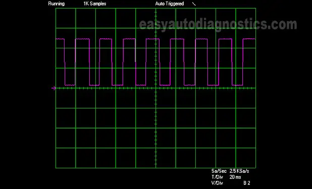
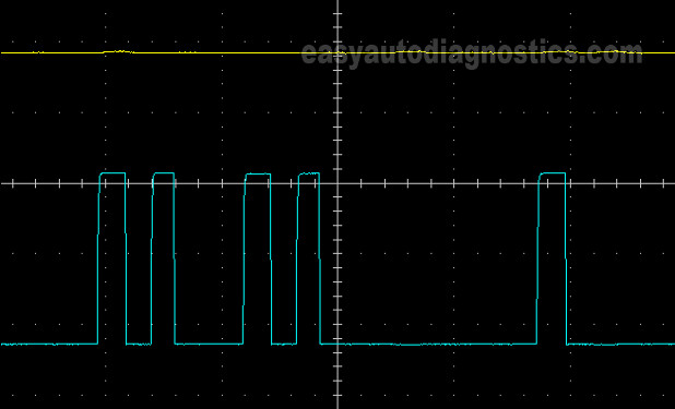
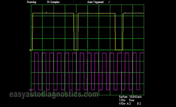
A digital signal is a DC voltage signal (remember that the analog signal is an AC voltage signal). This DC voltage signal looks and behaves completely different from an analog signal. Not only that, to produce this digital DC signal, the three wire type crank or cam sensor needs an external voltage power source (unlike the two wire type crank or cam sensor). When viewed in an oscilloscope's screen, it's displayed as a square wave, like the ones pictured below.
The digital signal that the three wire type (Hall Effect sensor type) produces is a true ON/OFF signal, very unlike the analog signal that the two wire type sensor produces. If we were to use the light bulb example from the previous page, the light bulb would turn on immediately (not gradually) and turn off abruptly (not gradually). This is what causes the sensor waveform to look squared instead of wavy. Also, this turning ON and OFF the signal happens the entire time the Hall Effect Position sensor is being excited by whatever toothed disc it's in close proximity to.
Now, in case you're wondering if you need an oscilloscope to test these crank and cam signals the answer is no. You don't need an oscilloscope and you definitely don't need an automotive scan tool to test the CKP sensor or CMP sensor signals. Now, having said that, the absolute best way to test/verify the presence of these signals is with an oscilloscope, but since most folks don't own one, this article concentrates on using a digital multimeter (that can read Hertz frequency).
OK, now for the really important ‘working theory’ part that you need to remember is that: the CKP and CMP digital signals can be measured with a multimeter either in DC volts mode or in Hertz frequency mode or with an oscilloscope and that they need an external power source to create their signal. As a side note, a simple LED light can also be used to verify this signal (although this method is not a 100% foolproof way of diagnosing a CKP or CMP sensor).
What ‘Excites’ The Sensor To Produce Its Signal?
Before leaving the ‘working theory’ alone, I need to talk about one more thing. I'm sure you've noticed the term ‘toothed disc’ thru' out this article. This is some sort of disc with teeth that resembles a gear or a wheel with shutters on it. This disc is what ‘excites’ the sensor into producing its signal. These discs go by names such as: shutter wheel, reluctor wheel, armature, interrupter ring, and the like. The name depends on who built the vehicle and/or the specific type of position sensor being used.
These toothed discs rotate only when the engine is cranking and/or running. They are directly or indirectly connected to the crankshaft or camshaft. Although they all perform the same basic job of exciting the CKP or CMP sensor, they come in all shapes and sizes which are determined by the needs of the software and hardware of the fuel injection system installed in the vehicle.
Well, it doesn't really matter what they look like and it definitely doesn't matter one bit what they're called. The important thing to know is that the sensor works in conjunction with some sort of ‘toothed disc’ to produce its signal.
Where Are The CKP And CMP Sensors Located?
These sensors are located in several different places depending on the year, make and/or model that you're working on. Some of them are in very hard to reach places and this, in my opinion, is the only thing that complicates testing them.
Some of their more common locations are:
- In the distributors.
- On timing covers.
- Behind timing covers.
- On the engine blocks themselves. In this type of setup, the sensor goes thru' the block to reach its toothed disc. Examples of this are the GM 3.1 and 3.4L V6 engines.
- On transmission bell housings. Chrysler, Dodge, and Jeep cars and trucks are the major ones that use this setup.
- Behind the crankshaft pulley.
Now, if you don't know where your particular car's (or truck's) crank or cam sensor is at, this is where owning a good repair manual comes in handy (or Googling it on the internet).
Symptoms Of A Bad Crankshaft Position Sensor
We can take for granted that when a CKP sensor goes bad, your vehicle will not start. It'll crank but not start. But hey, a car (or truck) could not start due to a ton of different reasons like: a bad fuel pump, a bad ignition coil, a bad ignition control module, bad spark plug cables, etc. Therefore, it's not enough to say that your car or truck won't start, what you need to know are some of the measurable/testable effects/symptoms that a bad crankshaft position sensor has on the ignition system.
And so, if the crankshaft position sensor isn't creating a signal, then the measurable/testable effects of this condition are but not limited to:
- No fuel injector pulse.
- The Triggering device (whether it's the ignition control module or the F.I. computer) will not produce a Switching signal to the ignition coil.
- No spark coming out of the ignition coil or coils.
- On some makes, like Chrysler/Dodge/Jeep, the fuel injection computer will not continue to power the fuel pump or the ignition system with 12 Volts after an initial ten seconds or so.
What Tools Do I Need To Test The Crankshaft And Camshaft Positions Sensors?
You don't need expensive tools and/or expensive testing equipment to test these CKP and CMP sensors. Here's what you'll need:
- The car or truck's battery must be fully charged.
- A digital multimeter that can read Hertz frequency.
- A good repair manual. The repair manual will probably be just one of many information resources that you'll use to diagnose the CKP or CMP sensors on your car or truck.
- You'll need someone to help you crank the car's or truck's engine while you observe the readings on the multimeter.
- A fuel injector Noid light.
- You don't need an automotive scan tool (commonly known as a scanner).
- You don't need oscilloscope.


