This tutorial will help you to diagnose the Vane Air Flow (VAF) Sensor on the 1988, 1989, 1990, 1991, and 1992 2.2L Mazda 626 (with or without turbo).
NOTE: This tutorial also applies to: 1988-1992 2.2L Ford Probe, 1988-1991 2.2L Mazda MX6.
Contents of this tutorial at a glance:
- Symptoms Of A Defective VAF sensor.
- VAF Sensor Test Basics.
- VAF Sensor Circuit Descriptions.
- TEST 1: Making Sure The VAF Sensor Is Getting Power.
- TEST 2: Making Sure The VAF Sensor Is Getting Ground.
- TEST 3: Testing The VAF Signal With A Multimeter.
- TEST 4: Testing The VAF Signal With The Engine Running.
![]() You can find this tutorial in Spanish here: Prueba Del Sensor VAF (1988-1992 2.2L Mazda 626) (at: autotecnico-online.com).
You can find this tutorial in Spanish here: Prueba Del Sensor VAF (1988-1992 2.2L Mazda 626) (at: autotecnico-online.com).
Symptoms Of A Defective VAF Sensor
The most common symptoms of a defective vane air flow sensor Sensor are:
- A MAF sensor code.
- A tremendous lack of power upon acceleration.
- Black smoke coming from the tail-pipe.
- Vehicle may idle rough and stall.
The VAF sensor test is easy but there are a couple of things that have to be done first. The two most important are:
- Verify that the engine does not have any vacuum leaks.
- Verify that there are no ignition system misfires. A misfire condition will skew the results of the test you'll perform here.
If the above conditions exist, repairing them first will more than likely solve your vehicle's drive-ability issue without having to test the VAF sensor, if not continue with the VAF test in this article.
VAF Sensor Test Basics
OK, we're gonna' start by checking the basics. These are 12 Volts and Ground to the vane air flow sensor. After that, we'll test the actual performance of the VAF sensor.
I recommend using a digital multimeter for all tests where a multimeter is called for. Why? -you may ask. Only a digital multimeter will be able to keep up with and register the voltage output signal of the VAF sensor.
This voltage signal is directly related to amount of air the engine is breathing. Common sense tells us that the engine will breathe in more air at 2500 RPMs than at an idle of 900 RPMs.
So keeping this in mind, the voltage value on the multimeter will be greater at 2500 RPMs than at 900 RPMs
Now, when testing this voltage output signal, the important thing to know is not an actual voltage number at a specific RPM, but to look for crazy and extreme fluctuations in the voltage signal that do not correspond to the actual air intake (RPMs) of the engine. For example: If at idle the voltage reading starts to spike up and down without you accelerating the engine.
In the TEST 4 section of this article, I'll show how you'll use a base Volts reading at idle from the VAF sensor that will help you to confirm that the VAF sensor is bad or not.
VAF Sensor Circuit Descriptions

The safest way to test these circuits, and the method I always use, is using a wire piercing probe (you can see an example here: Wire Piercing Probe). Using this probe, I don't have to disconnect the VAF sensor's connector to probe the front of the female terminal and possibly risk damaging it.
Independent of the method you use, be careful not to damage the wire or the female terminal. Take all safety precautions.
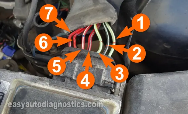
IMPORTANT: All of the tests are ON CAR TESTS, do not remove the vane air flow sensor from the vehicle or from its plumbing (all of the figures show the VAF sensor off of the vehicle just for illustration purposes only).
You'll notice that in the photo above, the VAF sensor's connector is numbered 1 thru 7. The only circuits that we are going to be concerned about in this tutorial are circuits 3, 4, and 6. Here's the description of each circuit below.
- Number 1- Fuel pump switch circuit.
- Number 2- Fuel pump switch circuit.
- Number 3- Sensor Ground thru' the ECM.
- Number 4- 12 Volts.
- Number 5- 9 Volts.
- Number 6- VAF signal.
- Number 7- Air Temperature Sensor Circuit.
We're ready to get started.

