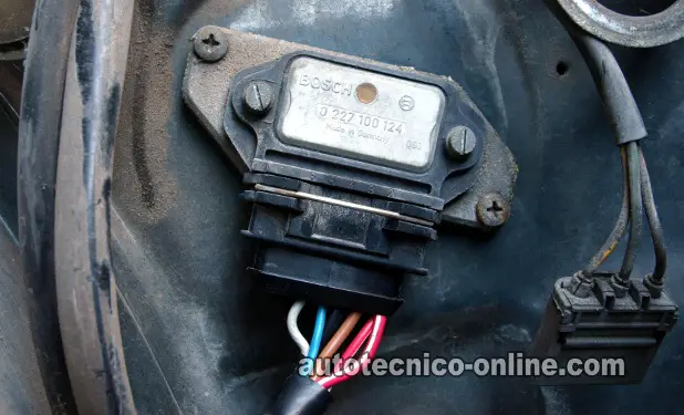
The Ignition Control Module
As stated in the first page of this article, what makes the ignition coil fire off spark is the turning ON and turning OFF of the Primary current by a Switching device. Which depending on the year, make, and model of the car you're working on (or driving) will either have an ignition control module (ICM) or a Power Transistor or an Igniter or the fuel injection computer handling the role of the Switching device.
The ignition control module accomplishes this ON/OFF action by simply interrupting the Primary current's path to Ground. This ON/OFF action occurs on the negative terminal of the ignition coil.
The beauty of it all, is that this Switching ON and OFF, of the Primary current, can be verified very easily, whether the ignition coil belongs to a distributor type system or to a Coil-On-Plug ignition system. This can be accomplished by using a test light in the majority of the cases or an LED light.
Now, since we live in an imperfect world, the ignition coils that can not be tested in this manner are the three-wire Coil-On-Plug ignition coils. Here are the test steps to test two-wire (two terminal) Ignition Coils:
Using an LED light:
- You'll need to identify which terminal, on the ignition coil is the power circuit and which is the Ground circuit.
- Normally labeled with a plus (+) or minus (-) symbol.
- Connect the black lead of the LED light to the negative terminal on the ignition coil.
- Connect the RED lead to battery voltage, although you could do this on the power terminal of the ignition coil, its preferable to connect it to the battery positive (+) terminal.
- When all is ready, have a helper crank the engine while you observe the LED light.
- If the Switching signal is present, the LED will flash ON and OFF.
Using a 12 Volt test light:
- You'll need to identify which terminal, on the ignition coil is the power circuit and which is the Ground circuit.
- Normally labeled with a plus (+) or minus (-) symbol.
- Connect the 12 Volt test light's alligator clip to the battery positive (+) terminal.
- With the probe end of the test light, touch the power terminal of the ignition coil.
- When all is ready, have a helper crank the engine while you observe the LED light.
- If the Switching signal is present, the test light will flash ON and OFF.
- Not all vehicles respond to the 12 Volt test light. In those cases you'll need to use the LED light method above.
Now, the reason why a three-wire Coil-On-Plug (COP) ignition coil can not be tested by the methods described above is that there is no negative terminal, that receives the Switching signal, exposed to attach any type of testing equipment. This terminal does exist, but is inside the ignition coil itself and connects directly to the Transistor (ignition control module, that's also inside).
The Crankshaft Position Sensor
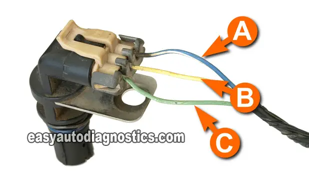
How does the ignition control module create the Switching signal? Well, besides needing power and Ground, the ignition module also needs a signal to let it know when to start switching the ignition coil ON and OFF. This is done by some sort of Triggering device. to make the long story short, the Triggering device is the crankshaft position sensor.
The crankshaft position sensor lets the ignition control module know exactly when to interrupt the ignition coil's Primary Current's path to Ground. Thus causing the ignition coil to spark at the exact time it needs to in the combustion cycle.
OK, these Triggering devices (piston position sensors) come in four basic types which are:
- Magnetic pulse generators.
- Hall Effect sensors.
- Metal detection sensors.
- Optical (photoelectric) sensors.
Each one produces a specific type of signal (Triggering signal). And of course are wired a little bit differently from each other.
The really cool thing is that all of these signals can also be easily tested. Some, like the Hall Effect type, can be tested with an LED light you can buy at Radio Shack or a multimeter.
Other types of crankshaft position sensors, like the magnetic pulse generator and the metal detection sensors, can be tested with a multimeter in AC Volts mode.
The best way to test them all is with an oscilloscope. But all testing methods work. I have used all techniques and each, depending on the circumstances, have worked for me and should for you too.
Since this article focuses on the ignition coil, let's move on to the next part: The Secondary circuit of the ignition coil.


