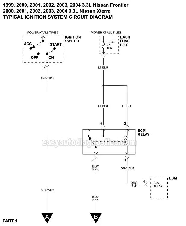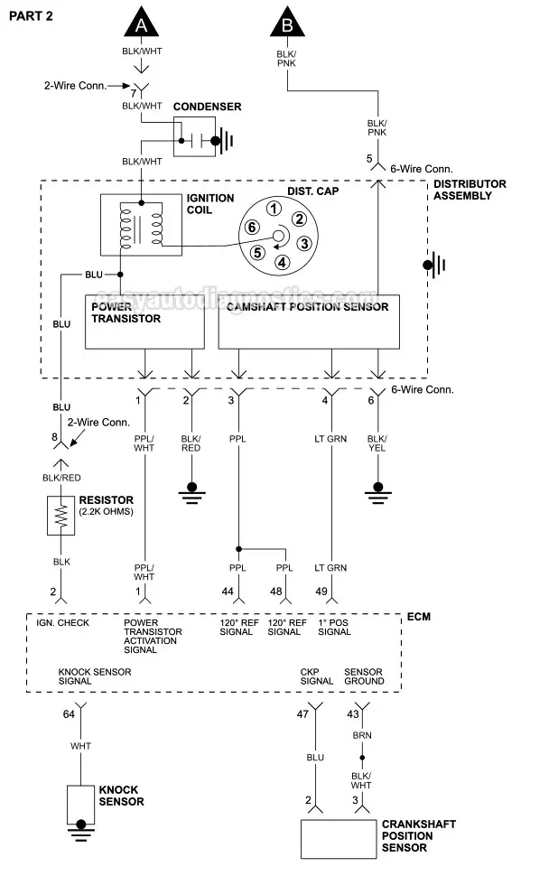

The above typical ignition system wiring diagram applies only to the 1999, 2000, 2001, 2002, 2003, 2004 3.3L Nissan Frontier and Xterra. It includes the following circuits: ignition coil, power transistor (ignition control module), and camshaft position sensor.
NOTE: The power transistor and the camshaft position sensor are part of the same assembly.
The ignition coil, power transistor, and the camshaft position sensor can be easily tested. The following tutorials will help you accomplish these tests:
- Power Transistor Test And Ignition Coil Test 3.3L Nissan (1996-2004).
- How To Test The Camshaft Position Sensor (3.3L V6 Frontier, Pathfinder, Xterra).
Ignition System Diagnostic Manual Download
Testing a no-start problem or a misfire due to an ignition system problem is not hard.
If you'd like to have access to a wiring diagram, ignition component connector pin-outs, and the entire testing procedure (for a no-start or a misfire problem) in one place, then take a look at the following diagnostic manuals in downloadable PDF format:

1999-2004 3.3L Frontier
Ignition System No-Start Problem Diagnostic Manual
$3.99 USD
All of the diagnostic information you need in one place to diagnose a no-start problem caused by the power transistor (ignition control module), the ignition coil, or the camshaft position sensor.
Also includes diagnostic tests to find out if the ignition system is causing a misfire problem.
Diagnostic manual comes with:
- Wiring diagram.
- Component pin outs.
- Connector pin outs.
- Complete step-by-step testing instructions.
- 31 pages.
The illustrations in the diagnostic manual are printer friendly!

2000-2004 3.3L XTerra
Ignition System No-Start Problem Diagnostic Manual
$3.99 USD
All of the diagnostic information you need in one place to diagnose a no-start problem caused by the power transistor (ignition control module), the ignition coil, or the camshaft position sensor.
Also includes diagnostic tests to find out if the ignition system is causing a misfire problem.
Diagnostic manual comes with:
- Wiring diagram.
- Component pin outs.
- Connector pin outs.
- Complete step-by-step testing instructions.
- 31 pages.
The illustrations in the diagnostic manual are printer friendly!
