As you're already aware, the engine is not gonna' crank and start if the starter motor has failed on your 1996-1997 3.3L Nissan Pathfinder.
In this tutorial, I'm gonna' show you how to test the starter motor and the inhibitor relay (starter motor relay).
This is an on-car starter motor test so you don't have to remove it to test it.
APPLIES TO: This tutorial only applies to the 1996-1997 3.3L Nissan Pathfinder and 3.3L QX-4 with an automatic transmission and without the factory built-in anti-theft system.
Contents of this tutorial:
- Starter Motor Test Basics.
- Tools Needed To Test The Starter Motor.
- TEST 1: Bypassing The Inhibitor Relay.
- TEST 2: Applying 12 Volts To The Starter Solenoid's S Terminal.
- TEST 3: Making Sure The Starter Motor Is Getting A Start Signal.
- TEST 4: Voltage Drop Testing The Battery (+) Cable.
- TEST 5: Making Sure The Inhibitor Relay Is Getting A Start Signal.
- TEST 6: Testing The Inhibitor Switch Signal.
- TEST 7: Making Sure The Inhibitor Relay Has Ground.
- Bypassing The Inhibitor Relay Is Not A Repair Solution.
- Jumper Wire Example.
- More Nissan 3.3L V6 Tutorials.
![]() You can find this tutorial in Spanish here: Cómo Probar El Motor De Arranque (1996-1997 3.3L Nissan Pathfinder) (at: autotecnico-online.com).
You can find this tutorial in Spanish here: Cómo Probar El Motor De Arranque (1996-1997 3.3L Nissan Pathfinder) (at: autotecnico-online.com).
WIRING DIAGRAM: You can find the starter motor circuit wiring diagram here: Starter Motor Circuit Diagram (1996-1997 3.3L Nissan Pathfinder).
Starter Motor Test Basics
When the starter motor fails, the engine will not crank when you turn the key to start it.
What will help to diagnose a starter motor problem is knowing how it activates to crank the engine.
The four main components involved in getting the engine to crank are:
- The ignition switch.
- The inhibitor switch (park/neutral safety switch on the automatic transmission).
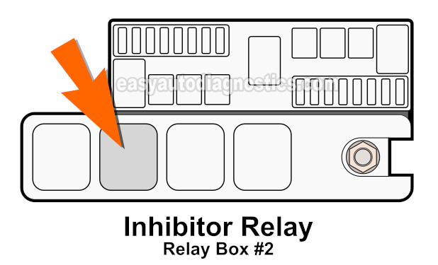
- The inhibitor relay. Located in the Relay Box #2.
- The starter motor.
In a nutshell this is how the starter motor cranks the engine:
- When you turn the key to start the engine the ignition switch sends 12 Volts to:
- The inhibitor switch.
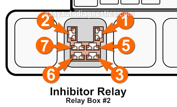
- Inhibitor relay terminal #3.
- If the transmission is in Park or Neutral, the inhibitor switch now routes the 12 Volts it got from the ignition switch to terminal #1 of the inhibitor relay.
- Once the inhibitor relay gets these 12 Volts from the inhibitor switch, it now activates and lets 12 Volts pass from the ignition switch to the starter motor.
- To be a bit more specific: power passes from terminal #3 to terminal #5 of the inhibitor relay.
- Terminal #5 connects to the S terminal on the starter motor's solenoid.
- Once the starter motor gets these 12 Volts, it now activates and cranks the engine.
You'll be able to better visualize this by consulting the following starter motor circuit wiring diagram: Starter Motor Circuit Diagram (1996-1997 3.3L Nissan Pathfinder).
For the starter motor to crank the engine, you should see the following at the inhibitor relay's socket (in the Relay Box #2):
- 12 Volts at female terminal #3 when you turn the key to start the engine.
- This is the Start Signal from the ignition switch.
- 12 Volts at female terminal #1 when you turn the key to start the engine.
- This is the Inhibitor Switch Signal from the inhibitor switch (park/neutral safety switch) on the automatic transmission.
- Ground present at terminal #2 at all times since this is a chassis Ground.
- Female terminal #5 is the one that transmits the 12 Volts from female terminal #3 to the starter motor.
In this tutorial, I'm gonna' show you how to check for the Start Signal, the Inhibitor Switch Signal, and the Ground that the inhibitor relay needs to activate the starter motor.
I'm also gonna' show you how to bypass the inhibitor relay to see if the starter motor cranks the engine.
With your test results you'll be able to find out if the starter motor or the inhibitor relay is causing the 'does not crank' problem of your 3.3L Nissan Pathfinder.
Tools Needed To Test The Starter Motor
Testing the starter motor does require some basic tools. The cool thing is that they aren't expensive. Here's a basic list of what you'll need:
- Remote starter switch.
- If you'd like to see what a remote starter switch looks like, you can follow this link: Innova 3630 Remote Starter Switch (Amazon affiliate link).
- You can either buy this tool online or you can buy it at your local auto parts store (AutoZone or O'Reilly Auto Parts, etc.).
- Multimeter or a 12 Volt automotive test light.
- If you don't have a multimeter or need to upgrade yours, check out my recommendation here: Tekpower TP8268 AC/DC Auto/Manual Range Digital Multimeter (Amazon affiliate link).
- A jumper wire.
- You can make your own. You can see an example here: Jumper Wire Example.
- A helper.
TEST 1: Bypassing The Inhibitor Relay
The first thing we're gonna' do is to activate the starter motor by bypassing the inhibitor relay. Photo 1 of 3 above shows the location of the inhibitor relay in Relay Box #2.
To bypass the inhibitor relay we're gonna' remove it from Relay Box #2 and then jumper female terminals #3 and #5 of its socket (see photo 2 of 3 above).
If jumpering terminal #3 and #5 makes the starter crank the engine then you can conclude that it's good and not behind the 'engine does not crank' problem you're trying to diagnose.
NOTE: Be careful not to damage the inhibitor relay connector's female terminals. The jumper wire terminals should be of the same thickness as the male spade terminals of the inhibitor relay to avoid damaging the female terminals of the socket.
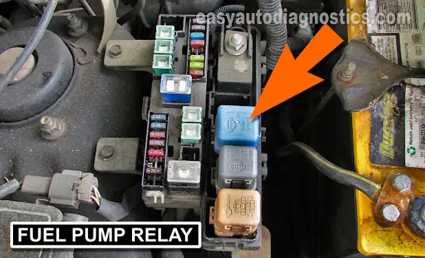
IMPORTANT: Remove the fuel pump relay as a safety precaution before starting this test. The fuel pump relay is located in Relay Box #2 (see photo 3 of 3).
These are the test steps:
- 1
Confirm that the automatic transmission is in Park.
- 2
Remove the fuel pump relay from Relay Box #2 (see photo 3 of 3)
This is a safety precaution. - 3
Remove the inhibitor relay from Relay Box #2.
- 4
Connect one end of the jumper wire to the female terminal labeled with the number 3.
- 5
Connect one end of the jumper wire to the female terminal labeled with the number 5.
- 6
Have your helper turn the key to start the engine.
- 7
The starter motor should crank the engine.
- 8
Remove the jumper wire when done with the test.
Let's examine your test results:
CASE 1: The starter motor cranked the engine. This is the correct and expected test result and lets you know that the starter motor is good.
Now, if the starter motor does not crank the engine with the inhibitor relay in place then there's a good chance that the inhibitor relay is:
- Not getting a Start Signal from the ignition switch.
- Not getting an Inhibitor Switch Signal.
- Not getting Ground.
Don't worry, I'm gonna' show you how to find out. The next step is check for the presence of the Start Signal. For this test to go to: TEST 5: Making Sure The Inhibitor Relay Is Getting A Start Signal.
CASE 2: The starter motor DID NOT crank the engine. This test result usually means that the starter motor is bad.
To be absolutely sure we need to do 3 things:
- Apply battery power to the starter solenoid's S terminal (TEST 2).
- Confirm that the starter motor is getting a Start Signal (TEST 3).
- Perform a voltage drop test on the starter motor's battery cable (TEST 5).
For the first test go to: TEST 2: Applying 12 Volts To The Starter Solenoid's S Terminal.
TEST 2: Applying 12 Volts To The Starter Solenoid's S Terminal

So far your first test has confirmed that the starter motor does not crank the engine when you bypass the inhibitor relay.
So in this section, we're gonna' apply 12 Volts from your Nissan's battery to the starter motor solenoid's S terminal.
If the starter motor is OK, then when the S terminal gets battery voltage it should crank the engine.
The easiest and safest way to apply battery power to the starter motor solenoid's S terminal is with a remote start switch.
If you don't have then you can find out what one looks like and where to buy one here: Innova 3630 Remote Starter Switch (Amazon affiliate link).
CAUTION: You'll need to raise your 3.3L Nissan Pathfinder to access the starter motor and perform TEST 2, TEST 3, and TEST 4. Use jack stands to keep it up. Don't trust the jack!
These are the test steps:
- 1
Make sure that the automatic transmission is in Park.
- 2
Disconnect the wire that connects to the starter motor solenoid's S terminal.
- 3
Connect one clip of the remote start switch to the male spade terminal.
- 4
Connect the other clip of the remote start switch to the battery positive (+) terminal.
- 5
Activate the remote start switch.
- 6
The starter motor should activate and crank the engine.
Let's examine your test results:
CASE 1: The starter motor cranked the engine. This is the correct test result and lets you know that the starter motor is OK.
If the starter motor is not cranking the engine when you turn the key to start the engine, then there's a good chance that the starter motor is not getting a Start Signal. Your next step is to go to: TEST 3: Making Sure The Starter Motor Is Getting A Start Signal.
CASE 2: The starter motor DID NOT crank the engine. This test result usually tells you that the starter motor is bad.
To be sure that the starter motor is bad you need to make sure that the cable that feeds it with battery current does not have a voltage drop. For this test go to: TEST 4: Voltage Drop Testing The Battery (+) Cable.


