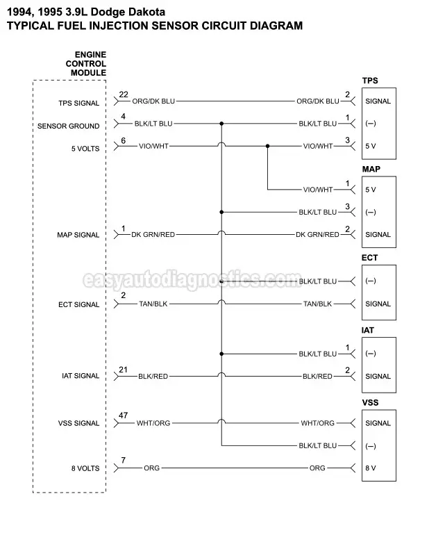
Here you'll find the typical fuel injection sensor circuit wiring diagram for the 1994 and 1995 3.9L V6 Dodge Dakota. You'll also find the power and Ground circuit wiring diagram of the fuel injection computer.
Wiring diagram includes the following circuits: Throttle Position Sensor (TPS), Manifold Absolute Pressure (MAP) Sensor, Engine Coolant Temperature (ECT) Sensor, Intake Air Temperature (IAT) Sensor, and the Vehicle Speed Sensor (VSS).
Contents of this tutorial at a glance:
DIAGRAM 1: Engine Management Sensors

TPS Sensor Pin Out

| Pin | Wire Color | Description |
|---|---|---|
| 1 | Black With Light Blue Stripe (BLK/LT BLU) | Sensor Ground |
| 2 | Orange With Light Blue Stripe (ORG/LT BLU) | TPS Signal |
| 3 | Violet With White Stripe (VIO/WHT) | 5 Volts |
Testing the throttle position sensor (TPS) can easily be done with a multimeter. You can find the TPS test here: How To Test The Throttle Position Sensor (1992-1995 3.9L Dodge Dakota).
MAP Sensor Pin Out

| Pin | Wire Color | Description |
|---|---|---|
| 1 | Violet With White Stripe (VIO/WHT) | 5 Volts |
| 2 | Dark Green With Red Stripe (DK GRN/RED) | MAP Signal |
| 1 | Black With Light Blue Stripe (BLK/LT BLU) | Sensor Ground |
Testing the manifold absolute pressure (MAP) sensor can easily and accurately be done with a multimeter. You can find the MAP sensor test here: How To Test The MAP Sensor (1992-1995 3.9L Dodge Dakota).
