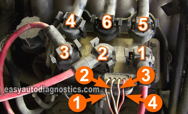
Coil Pack Circuit Descriptions Type 1

I've labeled each wire of the coil pack connector (in the photos) and below, you'll find the circuit descriptions for each number:
- Number 1: Switching signal circuit for cylinders 3 and 4.
- Number 2: Switching signal circuit for cylinders 2 and 6.
- Number 3: Switching signal circuit for cylinders 1 and 5.
- Number 4: Power Circuit (12 V) for all of the ignition coils within the coil pack.
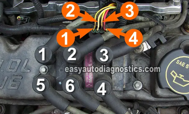
Coil Pack Circuit Descriptions Type 2

I've labeled each wire of the coil pack connector (in the photos) and below, you'll find the circuit descriptions for each number:
- Number 1: Switching signal circuit for cylinders 3 and 4.
- Number 2: Switching signal circuit for cylinders 2 and 6.
- Number 3: Switching signal circuit for cylinders 1 and 5.
- Number 4: Power Circuit (12 V) for all of the ignition coils within the coil pack.
Why Does The Ford Coil Pack Have 4 Wires?
The key to successfully troubleshooting the coil pack is to know that 3 individual ignition coils make up the Ford coil pack. Each of those three ignition coils has two towers that deliver spark to two cylinders simultaneously (I'll be referring to this as: paired cylinders).
Like in a conventional ignition system, each ignition coil (in the Ford coil pack) needs a power source and a switching signal to fire off a spark (if you want to read a primer on ignition coils, click here: Automotive Diagnostic Tips And Techniques: The Ignition Coil).
Therefore, three of the four wires provide the switching signal to each individual ignition coil within the Ford coil pack (you'll learn more about what this switching signal is below). The fourth wire supplies the juice to all of the ignition coils. Below, you'll find the circuit descriptions with photos that will help you to test and diagnose the Ford coil pack.
The beauty of the Ford coil pack type ignition system (on V-6 engine equipped vehicles) resides in the fact that they all use the same circuits no matter what the make (Ford or Mercury) or Model or type of coil pack (early or late design) used! The photos that, you'll find here and the circuit descriptions in them apply to ANY Ford (or Mercury) coil pack that is the same.
How The Ford Coil Pack Works On V6 Cars And Trucks
Here's a very simplified explanation of what it takes to make the Ford coil pack work. When you turn the key to crank and start the engine:
- Juice (12 Volts) flows from a fuse to a PCM relay.
- From this relay, these 12 Volts go to the power circuit of the coil pack connector.
- The coil pack in turn delivers 12 Volts to all of the ignition coils within it.
- As the engines starts to crank, the fuel injection computer receives a crankshaft position signal from the crankshaft position sensor.
- The PCM now starts to "switch" the Ground circuit of each individual ignition coil (within the coil pack) ON and OFF \(hence the name switching signal that you're gonna' see thru' out this article).
- It's this switching ON and OFF that makes each ignition coil fire off spark.
This spark is delivered to two cylinders at the exact same time. How? Well, this is possible since each ignition coil (within the Ford coil pack) has two towers instead of one. Therefore, the spark produced jumps out of both simultaneously.
So then, when the ignition coil (within the coil pack) that feeds cylinders 1 and 5 fires off a spark, the spark plugs for cylinders 1 and 5 spark at the exact same time. And so it goes for the cylinders 2 and 6 and cylinders 3 and 4.
OK, let's turn the page and get started testing.
