TEST 5: Testing The EGR Vacuum Regulator Solenoid (Part 2)

The second part of this test is to verify that the EGR Vacuum Regulator Solenoid is getting power (12 Volts). The third part (TEST 6) is to test to see if it is allowing vacuum to pass thru' to the EGR valve while you're driving the vehicle. For now, let's make sure its getting juice.
OK, this test can be performed with the EGR Vacuum Regulator Solenoid connected or disconnected from its connector. The test steps assume that you're testing the circuit with the connector connected to the vacuum Solenoid:
- Set your multimeter to Volts DC mode.
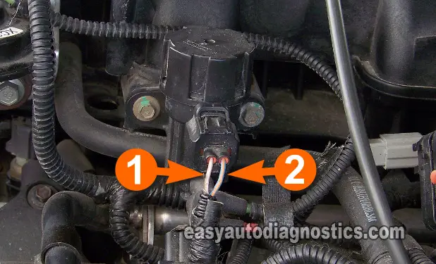
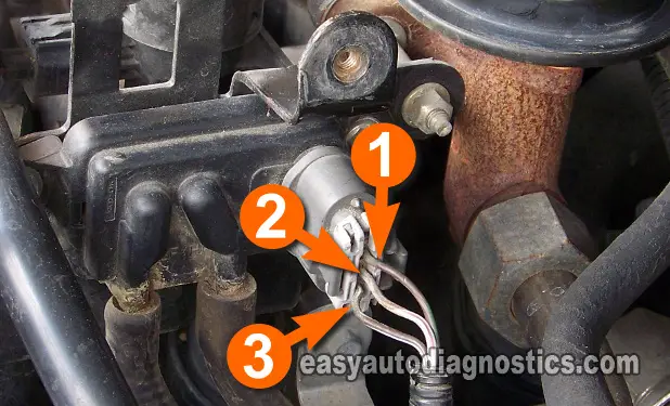
- Connect the red multimeter test lead (with an appropriate tool) to the wire identified with a number 2 in the photo above.
- Connect the black multimeter test lead to a good Ground point on the engine or to the battery negative (-) terminal.
- Have an assistant turn the key on or start the vehicle and notice the voltage reading on the multimeter.
Let's find out what your test results mean:
CASE 1: 12 Volts were present when the key was turned to ON. This indicates that the power circuit is good and delivering the goods to the EGR Vacuum Regulator Solenoid.
The next step is now to dynamically test the EGR Valve Vacuum Regulator Solenoid, go to: TEST 6: Testing The EGR Vacuum Regulator Solenoid (Part 3).
CASE 2: 12 Volts were NOT present when the key was turned to ON. Re-check all of your connections and multimeter setup.
If the multimeter still does not register this voltage, you must find out why these 12 Volts are missing. These missing 10 to 12 Volts will cause the check engine light (CEL) to illuminate on your instrument cluster. Repairing the cause should solve your EGR valve issue on your Ford car or truck.
TEST 6: Testing The EGR Vacuum Regulator Solenoid (Part 3)
The third part of testing the EGR Vacuum Regulator Solenoid is done while road testing your Ford (or Lincoln, or Mercury) car or truck. This test will let you know beyond a shadow of a doubt if the EGR Vacuum Regulator Solenoid is bad or not.
The engine in your Ford (or Lincoln, or Mercury) car or truck has to be at operating temperature before you start your road-test. This is important, since with a cold engine, the PCM will not activate the EGR valve system.
Here are the test steps:
- Disconnect the vacuum line or hose that is connected to the EGR valve (see photo 2 and 3 in the image viewer).
- Connect a piece of vacuum hose (that should be about 2 feet in length) to the vacuum line or hose you just disconnected as shown in photo 3.
- Snake the vacuum hose under the hood and secure it under the wiper arm.
- Connect a vacuum gauge to the end of the vacuum hose that's under the wiper arm.
- The vacuum gauge must be in such a position that you can easily read the gauge's needle as you're driving down the road.
OK, your mission is to verify that the vacuum gauge's needle moves up to 5 in.Hg only when you start to accelerate the car or truck (whether it's from a stand-still or you're already cruising). After the needle moves up to 5 in.HG, the vacuum gauge's needle should always drop down (immediately) to 0 (zero) in.HG when you let go off the accelerator pedal.
Let's find out what your test results mean:
CASE 1: The vacuum gauge's needle moved up to 5 in.HG when you accelerated the vehicle and then dropped to 0 in.HG when you released the accelerator pedal. This test result indicates beyond a shadow of doubt that the EGR Vacuum Regulator Solenoid is working correctly.
CASE 2: The vacuum gauge's needle DID NOT move up to 5 in.HG when you accelerated the vehicle and then dropped to 0 in.HG when you released the accelerator pedal. This indicates that the EGR Vacuum Regulator Solenoid is bad, replace it.
TEST 7: Testing The DPFE 5 V REFERENCE SIGNAL
The PCM provides the DPFE sensor with 5 Volts so that it can produce a PDFE sensor signal. Without these 5 Volts, the DPFE will not work at all. This test step checks for the presence of these 5 Volts.
This test can only be done with a multimeter, do not use a test light.
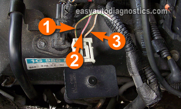
- Attach (with an appropriate tool) the red multimeter test lead to the wire labeled with the number 3.
- Connect the black multimeter test lead to a good Ground point on the engine or to the battery negative (-) terminal.
- Place the multimeter in DC Volts mode.
- Have your assistant turn the key to ON and notice the voltage reading on your multimeter.
- The multimeter should read 5 Volts.
Let's find out what your test results mean:
CASE 1: Your multimeter registered 5 Volts. This indicates that the PCM is providing the 5 V REFERENCE Signal to the DPFE. The next step is to verify that the PCM is providing a Ground return circuit for these 5 Volts, go to: TEST 8: DPFE Sensor Ground Return.
CASE 2: Your multimeter DID NOT register 5 Volts. Re-check all of your connections and repeat the test. The DPFE sensor will not work without this 5 V REFERENCE voltage and will set an EGR fault code that will light up the check engine light (CEL) on your instrument cluster. Repairing the cause of the missing 5 Volts will solve your EGR valve issue.
Some Tips And Suggestions
It's very rare for the DPFE sensor to have any type of issue with its 5 V REFERENCE voltage circuit. But if you do encounter this condition and you have triple-checked all of your multimeter's connections and set-up, then the two most likely causes are:
- An open-circuit problem in the wire (that feeds these 5 Volts to the DPFE sensor) between the PCM and the DPFE sensor.
- Or the PCM has fried.
Testing the two above conditions are beyond the scope of this article, but at least you have eliminated the EGR valve, the DPFE sensor, and the EGR Vacuum Regulator Solenoid as the cause of the EGR valve system malfunction.


