")
In this test tutorial, I'll show you how to test the mass air flow sensor to see if it's bad (and lighting up the check engine light) or not. This MAF test is done in 3 easy steps.
All you'll need, to test the MAF sensor (with this tutorial) is a multimeter that can read Hertz frequency (if you don't have one, I've made a recommendation on where you can buy a reasonably priced one below).
Contents of this tutorial:
- Symptoms Of A Bad GM MAF Sensor.
- What Tools Do I Need?
- Circuit Descriptions Of The MAF Sensor Connector.
- Where To Buy The MAF Sensor And Save.
- Basic Working Theory Of The GM MAF Sensor.
- TEST 1: Testing The MAF Signal Circuit.
- TEST 2: Testing The Power Circuit For 12 Volts.
- TEST 3: Testing The Ground Circuit.
- Oscilloscope Waveform Of The GM MAF Sensor.
![]() You can find this tutorial in Spanish here: Cómo Probar El Sensor MAF (2005-2007 3.5L GM) (at: autotecnico-online.com).
You can find this tutorial in Spanish here: Cómo Probar El Sensor MAF (2005-2007 3.5L GM) (at: autotecnico-online.com).
NOTE: In case this isn't the MAF sensor article you're needing, there are several more I've written and you can find some of them here:
- How To Test The GM mass air flow sensor (Early Type): Buick, Chevy, Olds, Pontiac 3.1L, 3.4L, 4.3L, 5.0L, 5.7L V6 Engines (1996-2005)
- How To Test The GM MAF Sensor: Buick, Chevy, Olds, Pontiac 3.8L V6 Engines (1996-2005)
- How To Test The GM Mass Air Flow (MAF) Sensor: 4.8L, 5.3L, 6.0L, and 8.1L V8 Engines (1999-2010)
- How To Test The MAF Sensor on 3.1L, 3.3L, and 3.8L Buick, Oldsmobile, Pontiac (1988-1996)
Symptoms Of A Bad GM MAF Sensor
The most obvious one is that the CHECK ENGINE light (CEL) will be on on your instrument cluster and driving you nuts. Here are a couple of others:
- A MAF sensor diagnostic trouble code (DTC) stored in your vehicle computer's memory.
- P0100: Mass Air Flow (MAF) Sensor Circuit Malfunction.
- P0101: Mass Air Flow (MAF) Sensor Circuit Range/Performance Problem.
- P0102: Mass Air Flow (MAF) Sensor Circuit Low Input.
- P0103: Mass Air Flow (MAF) Sensor Circuit High Input.
- Lean and/or Rich Diagnostic Trouble code(s).
- P0171: System Too Lean (Bank 1).
- P0172: System Too Rich (Bank 1).
- P0174: System Too Lean (Bank 2).
- P0175: System Too Rich (Bank 2).
- Fuel Trim diagnostic trouble code(s).
- No Power when you accelerate the car or truck.
- Black smoke coming from the tail-pipe.
- Your car or truck or SUV may idle rough and stall.
What Tools Do I Need?
A scan tool is one of those MUST have tools to be able check and diagnose today's modern cars and trucks, but for the tests in this article you don't need one.
These are the tools you'll need or may need:
- Multimeter
- A digital one that can read Hertz frequency is a must have tool to test the MAF sensor on your vehicle.
- If you need to buy one or are looking to upgrade, check out my recommendations here: Buying A Digital Multimeter For Automotive Diagnostic Testing.
- Wire Piercing Probe
- Although not an absolute must, this tool is a time saver of the first order. To see what this tool looks like, click here: Wire Piercing Probe.
Circuit Descriptions Of The MAF Sensor Connector
")
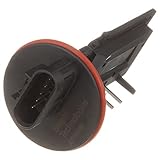
The MAF sensor covered by this tutorial has 5 wires coming out of the connector. Each wire (circuit) has a specific job to do and below, you'll find the description. Each of the 3 Tests, that make up this article, will use these circuit descriptions:
- Circuit labeled A:
- Yellow wire. MAF Sensor Signal
- Circuit labeled B:
- Pink w/ Black stripe wire. Ignition voltage (10 to 12 Volts DC).
- Circuit labeled C:
- Black w/ White stripe wire. Ground Circuit.
- Circuit labeled D:
- Tan wire. Air Temperature Sensor Circuit
- Circuit labeled E:
- Tan w/ Black stripe wire. Air Temperature Sensor Circuit (low reference = Ground).
Where To Buy The MAF Sensor And Save
The following links will help you comparison shop for the MAF sensor:


 34%
34%
Disclosure: As an Amazon Associate, I earn from qualifying purchases. Buying through these links helps support this site at no extra cost to you. Thanks for your support —it really means a lot!
Not sure if the MAF sensor will fit your particular GM vehicle? Don't worry, once you get to the site, they'll make sure it fits. If it doesn't, they'll find you the right one.
Basic Working Theory Of The GM MAF Sensor
The fuel injection computer needs to know the amount of air the engine is breathing to inject the correct amount of fuel (among several things) and keep your GM vehicle idling, running smooth, accelerating, polluting less, etc. For this, the PCM relies on the mass air flow sensor, among several of the sensors that monitor the engine and transmission.
The MAF sensor's job is to measure the amount of air the engine is breathing at any given RPM. It then converts this measurement into a Hertz frequency reading (as measured by a digital multimeter that can read Hz Frequency) and shoots it to the PCM. Here's what it looks like on a digital multimeter:
- At an idle of about 680 RPMs, the MAF sensor outputs about 3.2 K Hertz.
- Let me emphasize the words 'outputs about' because every vehicle will output a slightly different value depending on several conditions like: engine temperature, ambient air temperature, etc.
- At about at 1500 RPM;s the MAF signal output is about 4.2 K Hz.
- At 2500 RPMs it hovers around 5.2 K Hz.
As you can see, the more air the engine breathes (or the higher the RPMs) the higher the MAF output signal becomes, and of course the less air the engine breathes, the lower the reading on your digital multimeter.
Now, in testing the MAF sensor, you won't be looking for a specific Hertz (Hz) number at a specific RPM, but for crazy fluctuations in the signal that don't correspond to the amount of air entering the engine or NO SIGNAL AT ALL. OK, crash course is over, let's start testing.
TEST 1: Testing The MAF Signal Circuit
So far, in your troubleshooting tests, you've confirmed that:
- The MAF sensor has power.
- The MAF sensor has Ground.
With power, Ground and air flowing thru' it, the mass air flow (MAF) sensor has to produce a MAF signal. This MAF signal is then sent to the PCM for fuel injection calculations and the like.
In this last test, I'll show you how to test this MAF signal with your multimeter.
NOTE: To test the MAF sensor output signal, it's important that engine be at normal operating temperature. So, if it isn't already warmed up, go ahead and start'er up and let run for a few minutes. When ready, this is what you'll do:
IMPORTANT: The MAF sensor must be connected to its connector. You'll need to use a back probe on the connector or a wire piercing probe on the wire. You can see an example of this tool here: Wire Piercing Probe.
Let's get started:
- 1
Probe the wire identified with the letter A with the red multimeter test lead and an appropriate tool.
This is the yellow (YEL) wire of the MAF Connector. - 2
Put the multimeter in Hertz Frequency (Hz) mode
Don't have a digital multimeter that can read Hertz frequency? Check my recommendations here: Buying A Digital Multimeter For Automotive Diagnostic Testing. - 3
Connect the black multimeter test lead to the battery negative (-) terminal.
- 4
Start the already warmed up engine.
Once the engine is idling, note the Hertz reading on your multimeter at idle.
This reading may be stable (with only small fluctuations) or unstable with very extreme fluctuations. No matter what the instability in the reading, this will be your base reading. - 5
Manually accelerate the engine from the engine compartment as you watch the multimeter's frequency readings. The Hertz Frequency readings should increase as you rev up the engine.
- 6
When you let go off of the throttle and the engine returns to idle, the Hertz reading should come down to the base Hertz reading you observed in step 6 of this test.
At an idle of about 680 RPMs, the MAF sensor outputs about 3.2 K Hertz.
At about at 1500 RPM;s the MAF signal output is about 4.2 K Hz.
At 2500 RPMs it hovers around 5.2 K Hz. - 7
As you rev up/down the engine, the Hertz reading should increase/decrease
If the MAF sensor is defective, the Hertz value will stay stuck at one number as rev up the engine.
Let's take a look at what your test results mean:
CASE 1: The Hertz (Hz) signal rose smoothly and decreased smoothly as the engine was accelerated and decelerated respectively, then this indicates that the mass air flow (MAF) sensor is working correctly.
CASE 2: The Hertz (Hz) signal DID NOT rise smoothly nor decreased smoothly as the engine was accelerated and decelerated respectively. This generally indicates that the mass air flow (MAF) sensor is bad.
To make sure the MAF is bad, the next steps are to make sure its getting power and Ground. For the next test, go to: Testing The Power Circuit For 12 Volts.