TEST 5: The Switching Signal

OK, in test step, you're gonna' verify that the ignition control module (ICM) is creating and feeding the switching (activation) signal to the ignition coil that did not fire off spark.
For this test step you can not use a test light. You must use an LED light. Also, like in all of the previous test steps, when your helper cranks the engine, the engine will start (even tho' one of the three ignition coils is off), this is no cause for concern, just be careful, alert and take all necessary safety precautions.
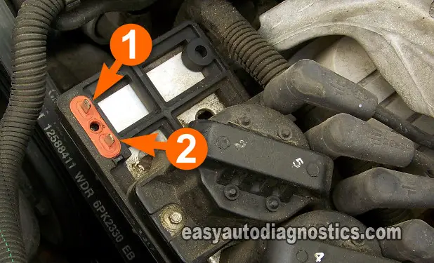
NOTE: You'll notice in the photo above that the ignition coil that feeds spark to cylinder 3 and 6 is removed. Arrow number 1 points to the terminal that feeds the coil with the activation signal and arrow number 2 points to the terminal that feeds 12 Volts. This same pattern (of arrow 1: activation signal and arrow 2: power supply) applies to the other ignition coils' terminals too.
These are the test steps:
- 1
With the ignition coil that did not spark still removed from the previous test (TEST 4).
- 2
Connect the black lead of the LED light to the male spade terminal identified by the number 1 in the photos above.
- 3
Connect the RED lead to the battery positive (+) terminal.
- 4
Have your helper crank the engine after you have made sure all of your connections are securely attached.
- 5
The LED light should flash ON and OFF the whole time the engine was cranked.
Let's take a look at what your test results mean:
CASE 1: The LED light flashed ON and OFF the whole time the engine was cranking. This test result tells you that the ignition module is activating the ignition coil to spark. This result also confirms that the ignition coil is bad and needs to be replaced only if you have:
- Confirmed that the ignition coil is not firing spark from its 2 towers (TEST 3).
- Confirmed that the ignition coil is getting 12 Volts (TEST 4).
- Confirmed that the ignition coil is getting its switching signal (TEST 5).
Taking all of these test results into account, you can conclude that the ignition coil is bad and needs to be replaced.
CASE 2: The LED light DID NOT flash ON and OFF the whole time the engine was cranking. This tells you that the ignition module is not activating the ignition coil. This result also confirms that the ignition control module is bad. Replace the ignition control module (ICM).
TEST 6: Other Common Misfire Causes

Over the past few years I've noticed a few other things that can cause a misfire code to set that are not caused by bad ignition coils. Although testing the following suggestions and/or tips are beyond the scope of this article, they just might inspire your next diagnostic move/test:
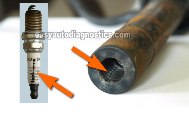
- Carbon tracks on the inside of the spark plug wires' boot and/or the spark plug boot (see photo above).
- You'll have to remove all of the spark plugs and visually inspect their ceramic insulators and the inside of each spark plug wire boot to see if carbon tracks have developed. The photo above shows you what a carbon track looks like inside the boot and on the spark plug.
- Broken spark plug.
- You'll have to remove them all and visually inspect them.
- An engine cylinder with lower compression than the rest.
- You'll have to remove all of the spark plugs and with a compression gauge, test all cylinders to get their compression readings/values.
- Intake manifold gasket leaking air into the engine.
- Bad fuel injector.
- Fuel pressure regulator leaking gasoline into its vacuum hose.
- For this test, all you have to do is remove the vacuum line that's attached to the vacuum line/hose nipple on the fuel pressure regulator itself and start the engine. If after about 30 seconds of engine run time the fuel pressure regulator starts leaking fuel from its vacuum hose nipple, the regulator is defective.
You can find these specific tests (like the engine compression test, bad fuel injector test) at troubleshootmyvehicle. Com:
- Engine Compression Test (GM 3.8L) (at: troubleshootmyvehicle.com).
- Fuel Injector Resistance Test (GM 3.8L) (at: troubleshootmyvehicle.com).
- Injector Noid Light Test (GM 3.8L) (at: troubleshootmyvehicle.com).
- How To Diagnose Misfire Codes P0300-P0306 (GM 3.8L) (at: troubleshootmyvehicle.com).
- How To Do A Cylinder Balance Test (GM 3.8L) (at: troubleshootmyvehicle.com).

If this info saved the day, buy me a beer!

