TEST 2: Testing The Ground Circuit

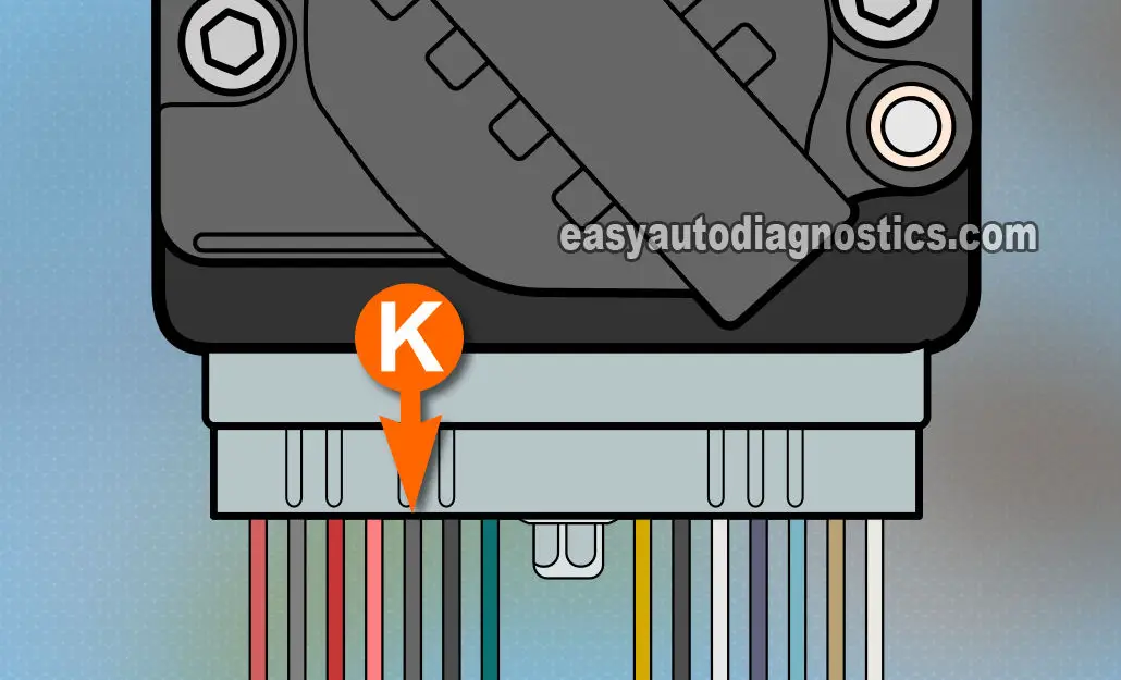
Here we'll check that the ignition control module (ICM) is receiving a good GROUND. The wire (circuit) that provides this Ground is the K circuit.
There's a good chance that your specific vehicle does not have this circuit (wire) in the connector. This is normal, since the module will get Ground thru' its case. You can skip this step and go to the next one.
NOTE: If your vehicle's ignition module does not have this Ground wire, take a look at B. Jones' feedback about his no-start problem due to the ignition module not getting a good Ground due to aluminum oxide (rust) on the module's case here: Real Life Case Study #1 (Thank you Bill for you feedback!).
These are the test steps:
- 1
Put the multimeter in Volts DC mode. Disconnect the ignition module from its connector.
- 2
Probe the wire labeled with the letter K with the black multimeter test lead and a wire piercing probe.
This wire is the BLACK with WHITE stripe wire of the ICM connector. - 3
With the red multimeter test lead, probe the battery positive (+) terminal.
- 4
You should see 10 to 12 Volts on the multimeter.
Let's take a look at what your test results mean:
CASE 1: Your multimeter registered 12 Volts. This tells you that the module does have a good path to Ground.
The next step is to make sure that the ignition module is feeding the crankshaft position sensor with power. For this test go to: TEST 3: Making Sure The Crank Sensor Is Getting Power.
CASE 2: Your multimeter DID NOT register 12 Volts. This means that the ICM is not getting Ground. This usually because the wire has an open somewhere between the connector and Ground.
Since the ignition module (ICM) needs this GROUND to function your next step is to restore this Ground.
TEST 3: Making Sure The Crank Sensor Is Getting Power

Now that you have verified the basics, in this test you're gonna' verify that the ignition control module is supplying 12 Volts to the camshaft and crankshaft position sensors.
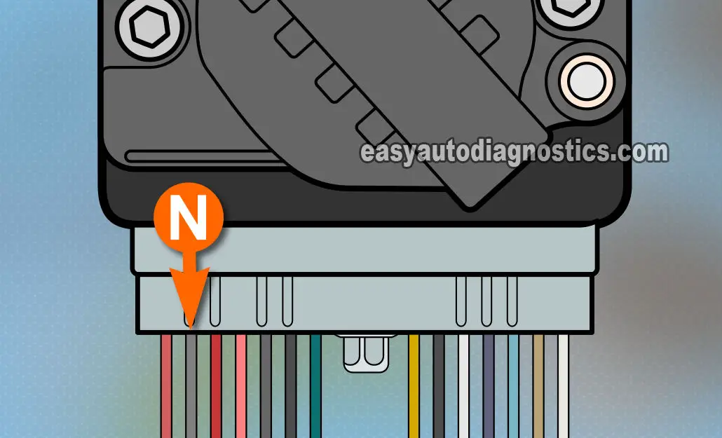
They're both fed power from the ICM thru' the same wire. This is the wire labeled with the letter N in the illustration above.
IMPORTANT: The ignition module must be connected to its electrical connector to be able to read the voltage the ICM is sending the crankshaft position sensor. I suggest using a wire piercing probe to check for this voltage.
These are the steps:
- 1
With the red multimeter test lead and a wire piercing probe, probe the WHITE with BLACK stripe wire of the connector shown in the figure above.
This is the wire labeled with the letter N in the photo above. - 2
With the black multimeter test lead probe the battery negative (-) terminal.
- 3
Turn the key to the ON position but don't crank or start the engine. You should see 10 to 12 Volts on the multimeter.
Let's take a look at what your test results mean:
CASE 1: Your multimeter registered 10 to 12 Volts. This tells you that the module is supplying power to the crank sensor (and cam sensor if equipped with one).
The next step is to verify that the crank sensor is producing the CRANK 18X signal. For this go to: TEST 4: Verifying The 18X CKP Sensor Signal.
CASE 2: Your multimeter DID NOT register 10 to 12 Volts. This result confirms that the module is fried and needs to be replaced.
Here's why: The ignition module is the only source of power for the crank (and cam) sensor, so if you have no power at all in this wire, the module is defective.
