Circuit Descriptions Of The Ignition Module

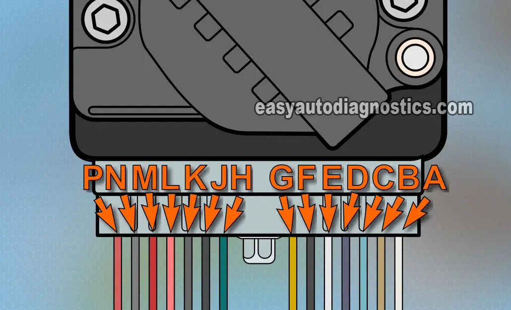
I'll begin by explaining the photo above. Each circuit is described by a letter. If you look closely at the connector (on the car), you'll find these exact same letters cast on it. For ease of testing in this article, I'll use the same letter method of circuit description. I'm sure you've noticed that the letters I and O are omitted (this is standard operating procedure in the electronics field to avoid confusing them with a number or other letters).
IMPORTANT- Some of the colors of the wires (below) may not necessarily be the colors on the vehicle you're working on. THIS IS NOT A CAUSE FOR CONCERN, because the circuit descriptions DO NOT change. YOU WILL be able to successfully diagnose this no-start condition with this information.
Also, you're specific vehicle may not have all of the wires (circuits) coming out of the ignition control module (ICM), this is also no cause for concern since it will be exact same ignition module (as long as the vehicle is a 3.8L V6). Remember, you won't be testing (and you don't need to) all of the circuits.
- A- WHITE wire.
- ECM control of ignition control module (after the 400 RPMs and above are achieved).
- B- TAN with BLACK stripe wire.
- 5 Volt BYPASS from ECM for Ignition Timing Control.
- C- LIGHT BLUE with BLACK stripe wire.
- CRANK Position Signal to ECM.
- D- PURPLE with WHITE stripe wire.
- Fuel Injection Control Signal to ECM.
- E- WHITE wire.
- Instrument Panel Tachometer Signal.
- F- BLACK wire.
- CAM signal from the camshaft position (CMP) sensor.
- G- YELLOW wire.
- CRANK (18X CKP) Signal from crankshaft position sensor assembly.
- H- LIGHT BLUE with WHITE wire.
- SYNC (3X CKP) Signal from crankshaft position sensor assembly.
- J- BROWN with WHITE stripe wire.
- CAM Signal from camshaft position (cmp) sensor.
- K- BLACK with WHITE stripe wire.
- Engine Ground (-).
- L- BLACK with RED stripe wire.
- Ground that ECM gets thru' the ignition control module.
- M- RED with BLACK stripe wire.
- Camshaft and crankshaft position sensor Ground (-).
- N- WHITE with BLACK stripe wire.
- 12 Volts to camshaft and crankshaft position sensors.
- P- PINK wire.
- Fused 12 Volts power for ignition control module.
Now, don't worry, it's not necessary to check every single wires' signal to test the ignition control module. All right, let's get started!
TEST 1: Checking For Power (12 V)

We'll begin by checking that the ignition control module is receiving 12 Volts. Space to test these circuits comfortably is almost nonexistent so, I recommend using a wire piercing probe to accomplish all of the tests in this article.
To see what a wire piercing probe looks like, go to: Wire Piercing Probe Review (Power Probe PWPPPPP01). Whatever method you use, the key here is to be careful. Remember to use common sense and take all safety precautions to solve the problem, not add to it.
Although the test below is done with a multimeter, you can also use a test light if you like.
- 1
Put the multimeter in Volts DC mode.
Don't have a digital multimeter? Need to buy one? Click here to see my recommendations: Buying A Digital Multimeter For Automotive Diagnostic Testing. - 2
Disconnect the ignition control module (ICM) from its connector.
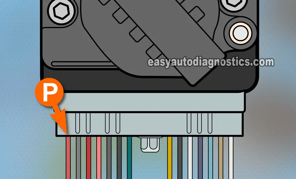
With the red multimeter test lead and a wire piercing probe, probe the PINK wire of the connector shown in the figure above. This is the wire labeled with the letter P in the illustration above. - 3
With the black multimeter test lead probe the battery negative (-) terminal.
- 4
Turn key ON with the engine OFF. You should see 10 to 12 Volts on the multimeter.
Let's take a look at what your test results mean:
CASE 1: Your multimeter registered 10 to 12 Volts. This tells you that the module is getting power.
The next step is to make sure the ICM is getting Ground. Go to: TEST 2: Testing The Ground Circuit.
CASE 2: Your multimeter DID NOT register 10 to 12 Volts. This test result lets you know that the ignition control module is not getting power.
You must find out why you're missing this voltage. Without this voltage the ignition control module (ICM) will not function. Re-check all of your connections and re-test. If voltage is still not present, you have just eliminated the ICM as being bad. After repairing the cause of the missing voltage, the vehicle should start.
