This type of EGR valve has made the auto repair industry and GM a ton of money over the years, since it's prone to carbon blockage. Well the good news is that this is an EGR valve and EGR valve system that is very easy to test and diagnose and this article will walk you thru' the entire diagnostic/troubleshooting process.
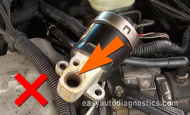
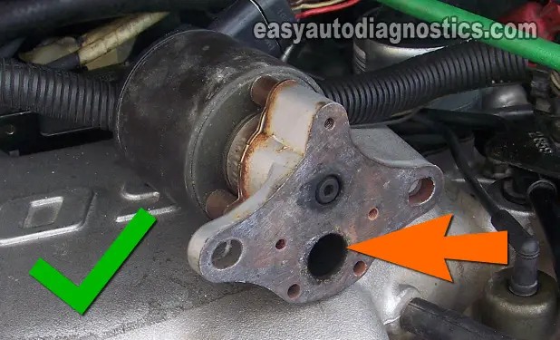
General Motors has used different types of electronic EGR valves and this article focuses on the Linear EGR valve from the mid 90's to the early 2000's. How can you tell them apart? By looking at the base of the EGR valve. To illustrate this, look at photo 3 of 4 and photo 4 of 4 in the image viewer above.
The EGR valve in photo 3 of 4 (with the red X) is not covered by this article and is tested differently. The EGR valve in photo 4 of 4 (with the GREEN check mark) is the one covered by this article. If you need the EGR valve test for the EGR valve marked with the X, you can find it here:
Contents of this tutorial:
- Common Symptoms Of A Bad EGR Valve.
- What Tools Do I Need?
- Circuit Descriptions Of The GM EGR Valve.
- TEST 1: First Things First.
- TEST 2: Testing The Power (12 V) Circuit.
- TEST 3: 5 Volt Reference Circuit.
- TEST 4: Verifying The Ground Circuit.
- TEST 5: Verifying The EGR Signal.
- TEST 6: Checking For Carbon Blockage.
- TEST 7: Clogged Intake Manifold.
- TEST 8: EGR Solenoid Resistance.
- TEST 9: Useful Notes.
- Real Life Case Studies From easyautodiagnostics.com Readers.
![]() You can find this tutorial in Spanish here: Cómo Probar La Válvula EGR de GM (Buick, Chevrolet, GMC, Oldsmobile, Pontiac) (at: autotecnico-online.com).
You can find this tutorial in Spanish here: Cómo Probar La Válvula EGR de GM (Buick, Chevrolet, GMC, Oldsmobile, Pontiac) (at: autotecnico-online.com).
Common Symptoms Of A Bad EGR Valve
This is not the most definitive list on the subject, but does cover the majority of symptoms I've seen on this type of EGR valve setup:
- EGR valve fault codes that light up the check engine light (CEL) on your instrument cluster.
- EGR valve fault codes:
- P0401 EGR System Flow Insufficient.
- P0403 EGR Solenoid Circuit.
- P0404 EGR System Performance.
- P0405 EGR Pintle Position Circuit Low Voltage.
- P1404 EGR Valve Stuck Open.
- P1406 EGR Valve Pintle Position.
- Rough idle.
- Really bad gas mileage.
- Lack of power as you accelerate the vehicle down the road.
- Car (or truck or mini-van) seems to run OK above 30 miles and hour but once you come to an idle, the engine barely stays running.
- Vehicle runs great, just the annoying check engine light is on with one of the above diagnostic trouble codes stored in the PCM's memory.
When something goes wrong with the EGR system, you usually see one of the following:
- Chunks of carbon blocking the EGR valve's pintle from fully seating in its seat.
- Now, as you may already know, exhaust gas cannot recirculate back into the engine at engine idle. If this happens, well the engine is gonna' idle rough and/or stall. exhaust gas recirculation is normally only permitted at hard acceleration or when the vehicle is already cruising at 30 mph or above and the vehicle is accelerated.
- When a piece of carbon blocks the EGR pintle from seating, you get one of the following diagnostic trouble codes: P1404 or P1406.
- The EGR passages inside the intake manifold get clogged with carbon.
- When this happens, you'll get a diagnostic trouble codes P0401.
This article will help you to diagnose all of the above DTCs, since it covers how to test the EGR solenoid (which I call the pintle motor), the EGR pintle position sensor and carbon blockages (the EGR solenoid and pintle position sensor all are inside and part of the EGR valve itself).
What Tools Do I Need?
A scan tool (Automotive Diagnostic Scanner) isn't needed to test the EGR valve on your GM car or truck. I'll show you how to test it without expensive tools. Here's what you'll need:
- A multimeter (don't have a digital multimeter? Need to buy one? Click here to see my recommendations: Buying A Digital Multimeter For Automotive Diagnostic Testing).
- A repair manual.
- For whatever remove and replace info you'll need that is not covered by this article.
Circuit Descriptions Of The GM EGR Valve
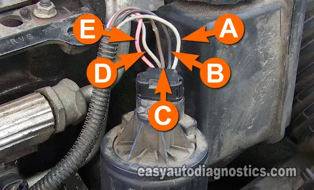
The connector on the EGR valve has 5 wires and normally the letters A thru' E are stamped on the EGR valve itself (but not always). I'll be using these same letters in all of the photos in the image viewer so that you'll know what wire to test. Below are the circuit descriptions:
- Circuit labeled A:
- EGR Valve Control (provided by the PCM).
- Circuit labeled B:
- Sensor Ground (provided by the PCM).
- Circuit labeled C:
- EGR Pintle Position Signal.
- Circuit labeled D:
- 5 Volt Reference (provided by the PCM).
- Circuit labeled E:
- 12 Volt Power Source.
The color of the wires is not important as long as you identify the wire (circuit) by its letter designation. Also, the EGR valve on your vehicle might have its connector connecting to it at a 90 degree angle or connecting straight down onto the EGR valve. This is also no cause for concern since they are one and the same when it comes to using this info to test them.
To test these circuits, it's not necessary to unplug the EGR valve's connector. What I recommend you do is to test for each signal with the connector connected using a wire-piercing probe. This is the easiest and the most effective way of getting at the signals. If you need to see what this tool looks like, click here: Wire-Piercing Probe.
TEST 1: First Things First
The most common problem on this type of GM EGR valve setup is carbon blocking the EGR pintle from fully extending and preventing exhaust gas flow into the intake manifold or blockage inside the intake manifold's plenum.
The EGR valve does go bad, but not very often. So the very first thing you need to do is to see if the EGR code that's lighting up the check engine light (CEL) or the rough idle your car is experiencing is due to a bad EGR pintle position sensor.
If you got EGR valve DTC P0403, you can skip this test and start with TEST 2.
We need a good and logical starting point for our tests, so first you'll check the EGR pintle position with a multimeter and depending on the result of this test, you'll know where to go from there.
NOTE: The EGR valve needs to remain connected to its electrical connector to perform this test. You'll need to back probe the connector or use a wire piercing probe on the wire. You can see an example of this tool here: Wire-Piercing Probe.
Let's get started:
- 1
Place your multimeter in Volts DC.
- 2
With the red multimeter test lead and an appropriate tool, probe the circuit labeled with the letter C.
- 3
Connect the black lead of the multimeter to a good Ground point on the engine or battery negative terminal.
- 4
Turn the Key on but don't crank or start the engine.
- 5
Your multimeter should display a voltage reading between 0.6 to 0.9 Volts DC if all is OK.
Let's take a look at what your test results mean:
CASE 1: Your multimeter displayed 0.6 to 0.9 Volts DC. So far so good since this is the correct and expected test result. Your next step is to go to: TEST 5: Verifying The EGR Signal.
The next step (TEST 5) is to remove the EGR from the intake manifold and manually induce the EGR valve to produce the entire range of the pintle position voltage values (by pushing the EGR's pintle in and out with a small screw-driver) to make sure the pintle position sensor inside the EGR valve is good.
CASE 2: Your multimeter displayed a DC voltage above 0.9 Volts. This is an indication that a piece or pieces of carbon are blocking the EGR valve's pintle from fully seating. Go to: TEST 6: Checking for Carbon Blockage.
CASE 3: Your multimeter DID NOT display any voltage or a very low voltage. Re-check all of your connections and redo the test.
If still no voltage or a voltage way lower than the 0.9 Volts specified, then this confirms the EGR P0405 (EGR Pintle Position Low Voltage) diagnostic trouble code.
This low or non-existent voltage output is usually due to the 5 Volt Reference Voltage (that powers the pintle position sensor inside the EGR valve) is missing. So, to check for this, go to: TEST 3: 5 Volt Reference Circuit.


