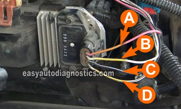
TEST 1: Power (12 Volts) Circuit Test

The first order of business,in diagnosing the ignition control module (ICM) and ignition coil, is to verify that both are getting juice (10 to 12 Volts). Without this voltage, the ignition system is not gonna' function. Both, the ignition module and ignition coil get power (10 to 12 Volts) from the same circuit, so by testing one component you're also testing the other.
IMPORTANT: It's critical to start here at TEST 1 and then go to the next indicated test(s) to successfully use this info and to diagnose your GM ICM or ignition coil. OK, the following test steps assume that you're testing this circuit with the ignition control module (ICM) connected to its connector and that you're using a multimeter, so:
- 1
Put the multimeter in Volts DC mode (don't have a digital multimeter? Need to buy one? Click here to see my recommendations: Buying A Digital Multimeter For Automotive Diagnostic Testing).
- 2
It's not necessary to disconnect the ignition control module (ICM). You'll probe the circuit identified with the letter A of the ignition control module connector.
- 3
With the red multimeter test lead and a suitable tool (like a Wire Piercing Probe), probe the circuit identified with the PINK wire of the Connector.
- 4
With the black multimeter test lead probe the battery negative (-) terminal.
- 5
Turn key ON with the engine OFF.
Let's take a look at your test results:
CASE 1: You got 10 to 12 Volts. This result lets you know that the fuse that feeds this circuit with voltage is OK. The next step is to test the Ground circuit, go to: TEST 2: Testing The Ground Circuit.
CASE 2: You DID NOT get 10 to 12 Volts. Recheck all of your connections and retest. If you still do not get the appropriate voltage, then the fuse or relay that feeds this circuit is bad. With this result you have eliminated the ignition control module (ICM) and ignition coil as the source of the NO-SPARK NO-START condition. Repairing the cause of this missing voltage should make the vehicle start.
TEST 2: Testing The Ground Circuit

Testing the Ground circuit is as easy as testing for the juice (in TEST 1). You can use a multimeter or a test light. The following test steps assume that you're using a multimeter and that you are testing the Ground circuit with the ignition control module (ICM) connected to its connector.
- 1
Put the multimeter in Volts DC mode.
- 2
With the black multimeter test lead and a wire piercing probe, probe the ignition module connector's BLACK with WHITE stripe wire.
- 3
This is the circuit labeled with the letter C.
- 4
With the red multimeter test lead probe the battery positive (+) terminal.
Let's take a look at your test results:
CASE 1: You got 10 to 12 Volts. This result lets you know that the Ground circuit is OK. The next step is to test the Switching signal that the ICM feeds the ignition coil, go to: TEST 3: Testing For The Ignition Coil Switching Signal.
CASE 2: You DID NOT get 10 to 12 Volts. Recheck all of your connections and retest. If you still do not get the appropriate voltage, then there's an open in the Ground circuit. With this result you have eliminated the ignition control module (ICM) and ignition coil as the source of the NO-SPARK NO-START condition. Repair the cause of this open in the Ground circuit and retest.
