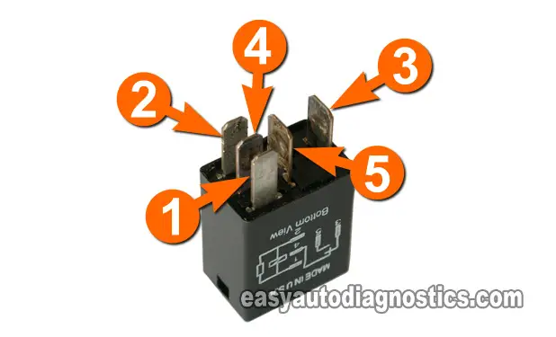
Every now and then, the need arises to bench test a Relay to find out if it's really bad or not.
This article will help you to bench test the Ford 20 amp multi-purpose Relay in a step by step fashion (there are two articles in site about bench testing a Ford Relay, the other is here: How To Bench Test A Ford Relay (Large Relay)).
Contents of this tutorial at a glance:
![]() You can find this tutorial in Spanish here: Cómo Probar En Banco Un Relé De Ford (Relé Pequeño) (at: autotecnico-online.com).
You can find this tutorial in Spanish here: Cómo Probar En Banco Un Relé De Ford (Relé Pequeño) (at: autotecnico-online.com).
For your cross reference information:
- Ford part #:
- F57B-14B192-AA
- AutoZone part #:
- Duralast 19283
- Duralast 20749
- O'Reilly Auto Parts part #:
- IDI 25-0136
- Other part #:
- STANDARD MOTOR PRODUCTS RY612
What Tools Do I Need To Test The Relay?
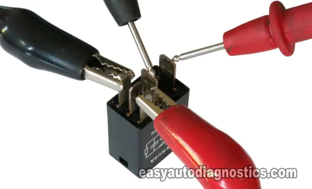
You'll need two very important things to bench test the relay and they are:
- Multimeter
- The multimeter can be digital or analog multimeter.
- If you need to buy one or are looking to upgrade, check out my recommendations here: Buying A Digital Multimeter For Automotive Diagnostic Testing.
- Jumper Wires
- You'll need two of them with alligator clips on both ends (you can make these yourself).
Relay Basics

The core purpose of a relay is to control a high amount of current with a smaller (lower) current. And it does this by having one circuit mechanically open or close another circuit.
These two circuits can be classified as:
- A high current circuit.
- This is the circuit that is opened and closed.
- This is the circuit that delivers the current to the component that needs it.
- A low current circuit.
- This the circuit that activates or deactivates the relay by 'opening' or 'closing' the high current circuit.
The relay that this article will help you test is a non solid-state type, which means that it activates with mechanical components.
Here's a very brief look and explanation of what the relay is made up of and how it works.
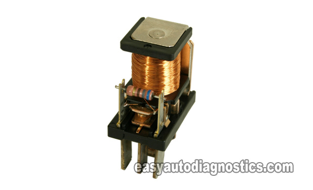
- Inside the relay's plastic cover, you'll find these core components:
- An Electromagnet
- This is a coil of wire wrapped around a soft iron core.
- When voltage flows thru it, it becomes a magnet.
- A movable Armature.
- This is the component that is moved from one contact to another, by the electromagnet's magnetic field, to complete the circuit (for the high current to pass thru').
- A Spring.
- After the relay is deactivated, the electromagnet's magnetic field collapses and the spring ensures the Armature returns to its original position.
- In this type of Relay, this spring is NOT the coil type. The spring is a leaf type spring.
- Several contacts.
- An Electromagnet
- When the relay's coil (electromagnet) gets energized (by having current flow thru' it), it moves the Armature to close against another contact.
- The Armature is the actual switch and completes or opens the circuit that will have the High current flowing thru' it.
- When the relay's coil gets de-energized, it loses it's magnetic power and thus let's go of the Armature.
- The Spring now acts on the Armature to place it back into its normally open position
- The High Current circuit now becomes ' open' , thus stopping any current from reaching the component that was being fed with it.
OK, working theory lesson is over, let's get testing in the next page.


