Testing For Spark At The Ignition Coil

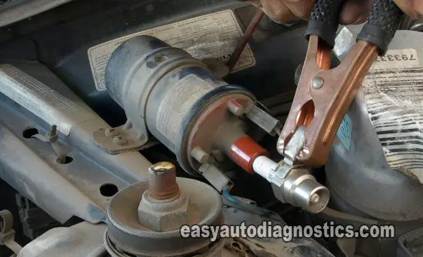
But this time I went straight to the source. I removed the cable from the ignition coil and held the spark tester directly to the ignition coil tower. As shown in the photo.
Once again I had my bud crank up the engine and still no spark. After this, I ran to my tool box to get my test light. I was afraid the Volvo would restart and that would be the end of the testing.
Testing For 12 Volts At The Ignition Coil

I got back with the 12 Volt test light and checked to see if the ignition coil was getting 12 Volts and it was.
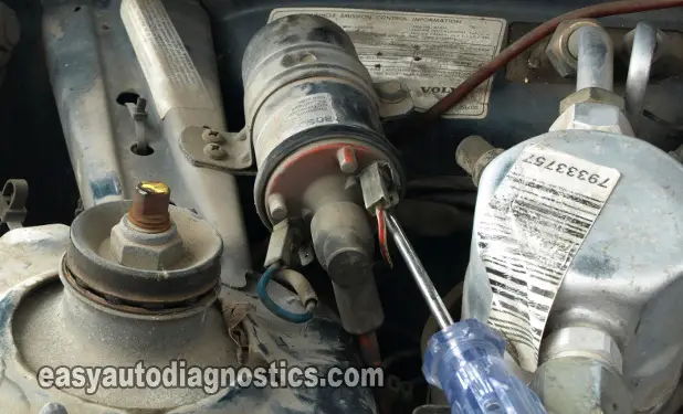
As you can see in the photo below (of the ignition coil) the coil has two connectors attached to it. One is the circuit that provides it with 12 Volts and the other provides the switching signal from the Switching Device (commonly known as the ignition control module). This circuit is labeled with a minus (-) symbol on the ignition coil.
Testing For The Switching Signal From The Ignition Module
Since I was getting 12 Volts, I could forget about this circuit and its components. The next step was to check for the Switching signal.
So then, I disconnected the negative terminal connector of the ignition coil. Then I put the alligator clip of the test light on the positive post of the Volvo's battery, after which I probed (with the test light ) the negative (-) connector itself while my bud cranked the engine one more time.
The 12 Volt test light did not flash ON and OFF. Let me explain to you what it was that I was looking for result-wise from this test.
If the test light had flashed ON and OFF, then I would have known beyond a shadow of a doubt that the ignition module was indeed doing its job and the ignition coil was bad.
But, since I did not get this flashing ON and OFF of the test light, I now knew that the ignition coil was not the source of the problem. If it doesn't receive this Switching signal, it won't work.
The ignition control module now came into scrutiny. If the ignition control module is not providing the Switching signal, then it's not doing its job.
I still could not condemn the ignition control module just on this alone. The module has to receive a Triggering signal to start the Switching signal to the ignition coil. But now I knew (by a process of elimination) from all of the tests I had done up until this point that the distributor cap, distributor rotor, the ignition cables, and the power circuit of the ignition coil were OK.
Here I ran into a wall so to speak, because now I needed a wiring diagram. I needed to know what circuit on the ignition module's connector was what.
Testing For Fuel Injector Pulse With Noid Light

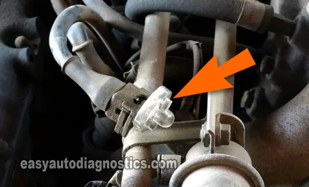
I still had one more test to perform. I needed to make sure that the fuel injection computer was pulsing the fuel injectors. Also, with this test I would indirectly test the crankshaft position sensor. Both the fuel injection computer and the ignition control module need a Triggering signal (from the crankshaft position sensor) to work (among other things).
This Triggering signal is provided by the crankshaft position sensor in the Volvo's distributor (it's a Hall Effect sensor). So by checking to see if the fuel injection computer is pulsing the fuel injectors with a fuel injector Noid light, then I'll know (indirectly) that the ignition module is also receiving this signal.
OK, the result of this test was that the fuel injection computer was indeed pulsing the fuel injectors. How did I know this? Because, once again my bud cranked up the Volvo and the Noid light flashed ON and OFF.
If I would have received NO flashes on the Noid light, then I could suspect that there was something wrong with the crank sensor and my diagnostic would then take a different path.
So far, by direct or indirect means I had eliminated the ignition coil, the distributor cap, distributor rotor, ignition cables (spark plug wires), the power circuit of the ignition coil, and the crank sensor.
