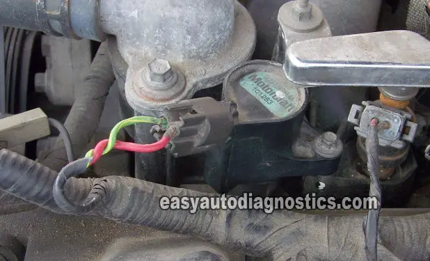
Ignition Coil Basics

To effectively diagnose the Coil-On-Plug ignition system (the type with two wires in the coil's connector), we need to know two basic pieces of information about the Coil-On-Plug ignition coil. Let's have a look.
First: we need to know how the Coil-On-Plug ignition coil works. More specifically, what the two wires (circuits) that are attached to it do (this is the ‘working theory’ I'm always referring to).
Second: How to test the ignition coil itself (either on the car or off). More specifically: testing for spark and testing the two circuits attached to it for their respective signals.
So, once we know what the circuits do, then testing them is easy. And of course, here you'll get the best testing strategy you're gonna' ever come across.
A Scan Tool Is Not Required To Test Coil-On-Plug Ignition
Also, knowing some working theory and some tests will help you diagnose the vehicle when a scan tool is not available. Or in cases when it's available but the vehicle (due to its age) does not support misfire diagnostics (misfire codes).
As you might already know, even if the vehicle does support misfire code diagnostics. Replacing the Coil-On-Plug ignition coil isn't always the solution to the misfire code that's lighting up the check engine light on the instrument cluster.
The bottom line is that a scan tool (Automotive Diagnostic Scanner) is not required to test a Coil-On-Plug ignition system.
Coil-On-Plug Ignition Circuits And Testing Basics
One wire of the Coil-On-Plug ignition coil is the power circuit that delivers 12 Volts. The other wire is the Switching signal circuit. This Switching signal comes from the ignition control module. this module may be in the ECM or mounted somewhere in the engine compartment. Three basic tests are done to test that these signals are indeed present in each circuit.
These are the three tests that have to be done to test for a bad ignition coil (Coil-On-Plug):
- Testing for spark. This is the very first thing that has to be done.
- Testing the power circuit for battery voltage (12 Volts).
- Testing the remaining wire (circuit) for the Switching signal.
Lets examine in more details all three of the above statements in the next headings.
Always Test For Spark First
The Coil-On-Plug ignition coil has to be removed from the vehicle and a spark tester attached to the coil-On-Plug Boot. The spark tester that I recommend to use is the HEI spark tester. This tester will produce a dependable result that you can trust. This tester is NOT expensive at all and you can pretty much buy it anywhere (online, auto-parts store, tool trucks, etc.).
If you have never heard of or seen this tool before or what it can do to help in your diagnostic tests, then I recommend the following article (within this site): The HEI Spark Tester.
We'll go into very specific details in the next page on how to perform the spark and how to interpret the tests results.
Test The Power Circuit Second
Testing for voltage is a no-brainer. But this is something that is easily overlooked. Here are some basic guidelines on the power circuit of the Coil-On-Plug:
- On the majority of the Coil-On-Plug systems:
- The individual ignition coils share the same fuse and/or relay that feeds the 12 Volts. If this fuse is blown, none of the ignition coils will fire and the vehicle will CRANK BUT NOT START.
- If one ignition coil out of the bunch isn't getting juice, then the most likely cause is an open-circuit problem in that specific circuit for that specific ignition coil and not the fuse or relay. Consulting a wiring diagram is the best way to find out.
- The voltage can be tested with:
- A multimeter. This is the fool-proof way but not the fastest sometimes.
- A Test Light. This is the fastest but not the most fool-proof way of testing for voltage.
- And it's done this way:
- With the connector connected or not (doesn't matter) probe the power circuit.
- Which one is it? To find out probe both with the key in the RUN position and the connector disconnected. Since the connector only has two wires, one of the two will have the 12 Volts. On Chrysler/Dodge/Plymouth vehicles, you'll have to crank the engine while testing for this voltage.
- This voltage should be the second item to be tested after performing a spark because:
- Will confirm if the NO SPARK result is due to the lack of voltage.
Test The Switching Signal Circuit Third
The third part of the test is testing and verifying that the Switching signal is present at the remaining wire (circuit) of the Coil-On-Plug's connector.
So, what's the Switching signal? The Switching signal is just a short-hand way of describing how the ignition control module (this is the Switching device) completes the path to Ground of the voltage flowing inside of the ignition coil and then how it interrupts (opens) this path to Ground. It's this ON/OFF action that induces the ignition coil to spark.
Most of the Coil-On-Plug ignition systems have the 'ignition control module' function integrated within the ECM. Only the older vehicle (mid 90s on back) have the ignition control module externally mounted somewhere in the engine compartment.
It doesn't matter where it's (the ignition module) located, this Switching signal is tested at the Coil-On-Plug and it's a very easy, easy test.
Alright, lets see some of this stuff in action in the next pages.
