TEST 2: Making Sure The CKP Sensor Is Getting Ground

If you've reached this point, you've confirmed that the crankshaft position sensor is getting power in TEST 1. Now, we need to make sure that the PCM is feeding the crank sensor with Ground.
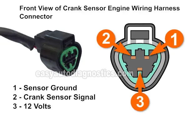
This Ground is fed by the wire that connects to the crank sensor engine harness connector labeled with the #1 in the illustration above.
NOTE: Avoid probing the front of the crank sensor engine wiring harness connector with your multimeter's test lead or you run the risk of damaging the terminal. I recommend that you use a back probe or a wiring piercing probe to check for Ground.
This is what you need to do:
- 1
Place your multimeter in Volts DC mode and unplug the crank sensor from the engine wiring harness connector.
IMPORTANT: This test is done on the engine wiring harness crank sensor connector and NOT on the sensor's connector. Recall that the engine wiring harness crank sensor connector has female terminals. - 2
Connect the black multimeter test lead to the BLK wire of the crank sensor connector. This is the wire that connects to the female terminal identified with the number 1 in the illustration above.
- 3
Connect the RED lead directly on the battery's positive (+) terminal.
- 4
Your multimeter should register 10 to 12 Volts with or without the Key in the ON position (if the BLK wire is feeding the crank sensor with Ground).
Let's interpret your test results:
CASE 1: The multimeter showed 10 to 12 Volts. Then all is good in this circuit and the CKP sensor is getting Ground.
The next step is check that the crank sensor is creating a crankshaft position signal, go to: TEST 3: Making Sure The CKP Sensor Is Creating A Crankshaft Position Signal.
CASE 2: The multimeter DID NOT show 10 to 12 Volts. This indicates that the CKP sensor doesn't have a good path to Ground. Without a path to Ground, the CKP will not work and your Mitsubishi Galant will 'crank but not start'.
Altho' it's beyond the scope of this tutorial, your next step is to find out why this Ground is missing and restore it. Repairing the cause of this missing Ground should solve your vehicle's no-start problem.
TEST 3: Making Sure The CKP Sensor Is Creating A Crankshaft Position Signal

OK, this is the final test (and the one you signed up for). In this test step, we're gonna' verify that the crank sensor is actually creating a crankshaft position signal.
The one thing you need to keep in mind, to get an accurate test result, is to manually turn the engine using a socket and ratchet wrench (on the crankshaft pulley).
In case you're wondering: 'Why turn the engine over by hand?' This is to ensure that you get a very accurate test result.
These are the steps:
- 1
Disable the ignition system by disconnecting the distributor from its electrical connectors. This is important!
- 2
Place your multimeter in Volts DC mode.
IMPORTANT: The crank sensor must be connected to its engine wiring harness connector for this test! - 3
Connect the red multimeter test lead to the BLU wire with an appropriate tool. The BLU wire connects to the connector terminal identified with the number 2 in the illustration.
You should use a back-probe or a wire-piercing tool to attach to your multimeter to check for this crankshaft position signal (Wire Piercing Probe). - 4
Connect the multimeter's black lead directly on the battery negative (-) terminal or a good Ground point on the engine.
- 5
Turn the key to the On Position but don't crank the engine. This will power up the crank sensor.
- 6
With an appropriate tool, turn the crankshaft pulley by hand. Do not crank the engine with the key from inside of the vehicle.
- 7
If the crank sensor is functioning correctly, your multimeter will register an ON/OFF voltage signal as you crank the engine by hand. 'On' will register 5 Volts on the multimeter and 'Off' will register 0.1 Volts.
Let's find out what your test results mean:
CASE 1: The multimeter registered the ON/OFF voltage values the whole time you hand cranked the engine. This test result confirms the crankshaft position sensor is working and is not the cause of your Galant's 'no-spark no-start' condition.
CASE 2: The multimeter DID NOT register the ON/OFF voltage values. This test result confirms the crankshaft position sensor is bad and needs to be replaced.
To explain this a bit further: You have:
- Checked/confirmed that the crankshaft position sensor is being fed power on the RED wire (TEST 1).
- Checked/confirmed that the crankshaft position sensor is being fed Ground on the BLK wire (TEST 2).
- In this test step, you confirmed that the sensor is not creating the ON/OFF voltage signal (On= 5 Volts, Off= 0.1 Volts).
Taking these 3 specific test results into account, you can conclude the crankshaft position sensor on your 2.4L Mitsubishi Galant is bad.
More 2.4L Mitsubishi Tutorials
You can find a complete list of 2.4L Mitsubishi tutorials here: Mitsubishi 2.4L Index Of Articles.
Here's a small sample of the tutorials you'll find in the index:
- How To Test The Fuel Injectors (2.4L Mitsubishi).
- How To Test The Throttle Position Sensor (2.4L Mitsubishi).
- How To Test The Engine Compression (Mitsubishi 1.8L, 2.4L).
- Testing A Bad Alternator: Symptoms And Diagnosis.
- How To Bench Test The Starter Motor.
- Blown Head Gasket Test (Mitsubishi 1.8L, 2.4L).

If this info saved the day, buy me a beer!


