TEST 2: Testing The Ground Circuit

In this test step, we're gonna' make sure that your 3.0L V6 Mitsubishi Montero's PCM is feeding the MAF sensor with Ground, since without this Ground the sensor won't work.
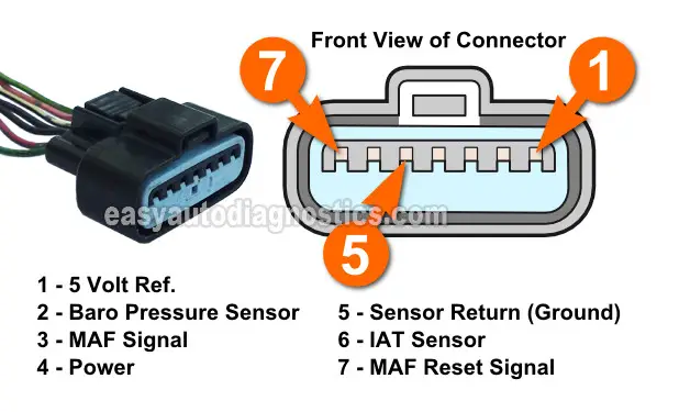
The wire that feeds the MAF sensor this Ground is the wire that connects to terminal #5 of the MAF sensor connector. As in TEST 1, we'll use the multimeter to check this circuit.
IMPORTANT: Be careful and do not short this circuit to battery voltage accidentally or intentionally or you'll fry the PCM. Using a digital multimeter to check this circuit is the safest way to check for Ground.
These are the steps:
- 1
Place the multimeter in Volts DC mode.
- 2
Connect the black multimeter test lead to the wire that connects to the connector terminal identified with the number 5 (see the illustration above) using an appropriate tool.
- 3
Connect the red multimeter test lead to the battery positive (+) terminal.
- 4
Turn the key ON but don't crank or start the engine.
- 5
The multimeter should register between 10 to 12 Volts DC.
Let's take a look at what your test results mean:
CASE 1: The multimeter registered 10 to 12 Volts DC. This is the correct test result and it indicates that the MAF sensor is getting Ground.
The next test is to verify that the MAF sensor is creating a good MAF signal based on the airflow the engine is breathing. For this test go to: TEST 3: Testing The MAF Signal Circuit.
CASE 2: The multimeter DID NOT register 10 to 12 Volts DC. This exonerates the MAF sensor as being bad, since without Ground, the MAF sensor will not work and this will light up the check engine light (CEL) on your instrument cluster.
Repairing the cause of the missing Ground will solve the problem with the MAF sensor.
TEST 3: Testing The MAF Signal Circuit

The MAF signal the sensor creates is based on the amount of air the engine is breathing. In really simple terms, this means that the MAF signal increases when the engine accelerates and decreases when the engine returns to its idle RPMs.
We can tap into the wire that carries this signal, with a Hertz frequency capable multimeter, and see/confirm that the MAF sensor is actually doing this.
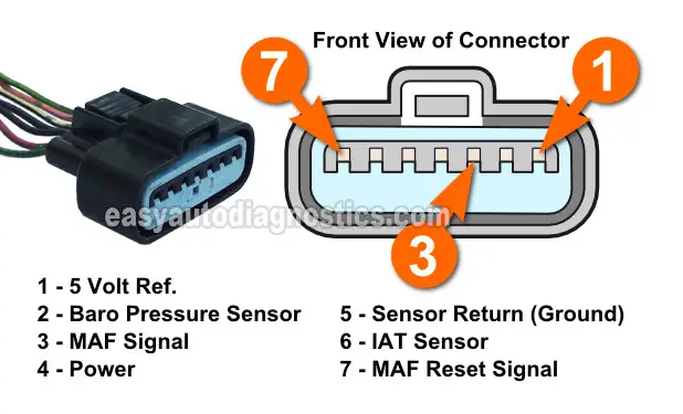
The MAF sensor supplies this MAF signal on the wire that connects to terminal #3 of the MAF sensor connector and this is the wire that we will tap into to check the sensor's performance.
If your Montero's MAF sensor is working correctly, you'll see this MAF Hertz frequency signal increase/decrease as you manually accelerate/decelerate the engine.
If the MAF sensor is bad, you'll see this Hertz frequency signal stay stuck in one value no matter how much you accelerate the engine.
NOTE: The MAF sensor must remain connected to its connector for this test to work. To access the signal inside the wire you'll need to use a back probe on the connector or a wire piercing probe on the wire. You can see an example of this tool here: Wire Piercing Probe.
OK, these are the test steps:
- 1
Put the multimeter in Hertz (Hz) frequency mode.
- 2
Connect the red multimeter test lead to the wire identified with the number 3 with a back probe or wire-piercing probe.
- 3
Connect the black multimeter test lead to the battery negative (-) terminal.
- 4
Start the engine and note the Hertz reading on your multimeter at idle.
Now, to give you a reference point, this Hertz value usually hovers around 10 to 14 Hertz at idle. This reading may be stable (with only small fluctuations) or unstable with very extreme fluctuations. No matter what the instability in the reading, this will be your base reading. - 5
Manually accelerate the engine from the engine compartment as you watch the multimeter's frequency readings. The Hertz frequency readings should increase.
At around 2,500 RPMs this Hertz reading will oscillate around 70 Hertz. - 6
Let go of the throttle and let the engine return to idle. The Hertz reading should come down to the base Hertz reading you observed in step 4 of this test.
- 7
Accelerate/decelerate the engine several times. The Hertz numbers on the multimeter should increase/decrease every time you accelerate/decelerate the engine.
Let's take a look at what your test results mean:
CASE 1: The Hertz (Hz) signal increased/decreased as the engine was accelerated/decelerated. This is the correct test result and it indicates that the mass air flow (MAF) sensor is producing a good MAF signal.
You still need to do one more test and this is to check that the MAF Reset Signal is being created. For this test, go to: TEST 4: Testing The MAF Reset Signal.
CASE 2: The Hertz (Hz) signal DID NOT increase/decrease as the engine was accelerated/decelerated. Then this indicates that the mass air flow (MAF) sensor is bad.
I'll explain why: You have confirmed the basics, which was checking/confirming the sensor is being fed power and Ground. Since the MAF sensor is getting both, then it should create a Hertz frequency signal that should increase/decrease as you accelerate/decelerate the engine. Since it did not, the MAF sensor is defective.
