TEST 5: Making Sure The Ignition Coil Is Getting 12 Volts

If the ignition coil isn't getting power (10 to 12 Volts), it's not gonna fire spark. So in this test, you'll check and confirm that it is indeed getting juice.
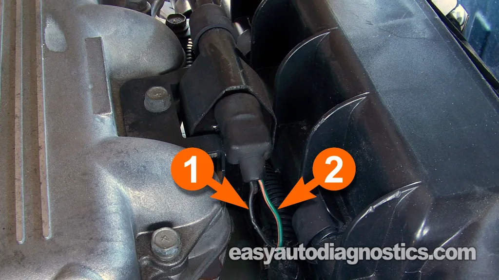
The wire that delivers these 10 to 12 Volts is the dark green with orange stripe (DK GRN/ORG) wire of the ignition coil's 2-wire connector.
IMPORTANT: 12 Volts are only supplied to the ignition coil when the engine is cranking or running. Just turning the key to the RUN position will not make these 12 Volts available on the DK GRN/ORG wire.
These are the test steps:
- 1
Disconnect the ignition coil from its connector.
- 2
Connect the black multimeter test lead to the battery negative (-) terminal.
- 3
Place your multimeter in Volts DC mode.
- 4
Gently probe the terminal that connects to the DK GRN/ORG wire with the red multimeter test lead.
CAUTION: Be careful that the multimeter probe doesn't damage the female terminal, or you'll have to get a new connector. - 5
Have your helper crank the engine.
NOTE: This voltage is only available when the engine is cranking or running. - 6
You should see 10 to 12 Volts on your multimeter.
Let's interpret your test result:
CASE 1: You got 10 to 12 Volts. So far so good, the next step is to check to see if the ignition coil is receiving an activation signal from the ignition module. For this test go to: TEST 6: Making Sure The Ignition Coil Is Getting An Activation Signal.
CASE 2: You DID NOT get 10 to 12 Volts. Without this voltage the ignition coil will work.
Resolving this power issue should solve your no-start condition. The most likely cause is a bad crankshaft (CKP) position sensor (which is located inside the distributor).
Your next step is to go: TEST 7: Making Sure The CKP Sensor Is Getting Power.
In case you're wondering what the CKP sensor has to do with these missing 10 to 12 Volts: the power supply to the ignition coil is controlled by the engine's cranking/running status. The crankshaft position sensor (CKP) plays a critical role in this process. If the CKP sensor fails, the fuel injection computer won't receive the engine RPM input it needs.
Without this RPM input, the computer figures the engine isn't cranking or running and it won't activate the Automatic Shutdown (ASD) relay. The ASD relay is responsible for supplying power to several key components, including the ignition coil. So, if the CKP sensor fails and the ASD relay does not get activated, the ignition and fuel system won't be powered up with the necessary 12 Volts and the engine is not gonna start.
TEST 6: Making Sure The Ignition Coil Is Getting An Activation Signal

The ignition coil gets an activation signal from the fuel injection computer and in this test section, we'll make it's being delivered when cranking the engine.
You can use a test light or an LED light. This test is performed with the engine being cranked, so be careful and take all necessary safety precautions.
The following test steps assume that you're using an LED light to test for an activation signal
NOTE: You can see an example of the LED light and where to buy it here: The LED Light Test Tool And How To Make One.
These are the test steps:
- 1
Disconnect the ignition coil from its connector.
- 2
Insert the black lead of the LED light into the female terminal of the connector that connects to the BLK/GRY wire.
The BLK/GRY wire is the one that feeds the activation signal to the ignition coil.
NOTE: Make sure that the black lead of the LED light makes a tight connection in the female terminal. - 4
Insert the red lead of the LED light into the female terminal of the connector that connects to the DK GRN/ORG wire.
NOTE: Make sure that the red lead of the LED light makes a tight connection in the female terminal. - 5
Have your helper crank the engine while you observe the LED light.
- 6
The LED light should flash ON and OFF the whole time the engine is cranking.
Let's take a look at your test results:
CASE 1: The LED light flashed ON and OFF. This is the correct test result and it confirms that the ignition coil is receiving an activation signal.
This test result confirms the ignition coil is bad and needs to be replaced if you have:
- Confirmed none of the spark plugs are sparking (TEST 1).
- Confirmed the ignition coil high tension wire is not sparking (TEST 3).
- Confirmed the ignition coil tower is not sparking (TEST 4).
- Confirmed the DK GRN/ORG wire is delivering 10 to 12 Volts (TEST 5).
- Confirmed in this test section that the ignition coil is receiving an activation signal.
This test result also confirms that the crankshaft position sensor (within the distributor) is GOOD. Replacing the ignition coil will solve the engine's 'no-spark no-start' problem.
CASE 2: The LED light DID NOT flash ON and OFF. Re-check all of your connections and retry the test again.
If the LED light still does not flash ON and OFF, the next step is to start testing the crankshaft position sensor, go to: TEST 7: Making Sure The CKP Sensor Is Getting Power.
TEST 7: Making Sure The CKP Sensor Is Getting Power
The crankshaft position (CKP) sensor, in your 3.0L V6 equipped Chrysler (or Dodge or Plymouth) is located inside the distributor.
The CKP sensor assembly is two sensors in one (a CMP and CKP sensor). Not only that, it's an optical type sensor. And of course, I'm gonna show you a very easy way to test it.
The very first thing that has to be checked, when testing the crankshaft position sensor, is that it is getting power.
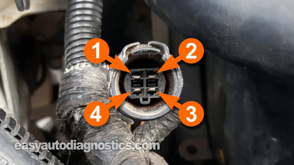
Power is in the form of 8 Volts which come from the fuel injection computer and delivered by the orange (ORG) wire of the distributor's 4-wire connector.
The ORG wire connects to the female terminal labeled with the number 3 in image 1 of 2 in the image viewer above.
Let's get going:
- 1
Place the multimeter in Volts DC mode.
- 2
Disconnect the distributor 4-wire connector.
- 3
Connect the black multimeter test lead to the battery negative (-) terminal.
- 4
Have your assistant turn the key to the ON position but not crank or start the engine.
- 5
Gently probe the terminal labeled with the number 3 with the red multimeter test lead.
Terminal 3 should connect to the orange wire.
IMPORTANT: This test is done on the engine wiring harness connector and not the connector that belongs to the distributor itself. - 6
The multimeter should register between 6 to 8 Volts DC.
Let's analyze your test result:
CASE 1: The multimeter displayed 6 to 8 Volts DC. Awesome, since this test result confirms the crank sensor assembly is getting power.
The next test is to verify that it's getting Ground, go to: TEST 8: Making Sure The CKP Sensor Is Getting Ground.
CASE 2: The multimeter DID NOT display 6 to 8 Volts DC. Recheck all your connections and retest.
If still the multimeter does not display the indicated voltage, then the CKP sensor itself is not bad. Without this voltage, the CKP and CMP sensor assembly will not work. Resolving the cause of this missing voltage will solve the no-spark no-start issue with your Chrysler car or mini-van.


