TEST 3: Testing The TP Signal

Up until this point, your tests have verified that the throttle position sensor is being supplied with 5 Volts and Ground. The next step is to see if it's producing a good signal that the PCM can use.
If the throttle position sensor (TPS) is working correctly, the multimeter will register a smooth increase in the DC voltage until the maximum voltage is reached, which is about 4.5 Volts DC.
Then, as you slowly release the throttle plate back to its closed position, the multimeter will display a gradual decrease in voltage till the initial base voltage is achieved (which you recorded in the beginning of the test).
If the TPS is bad, the voltage reading will stay stuck in one value or the voltage signal will have gaps as you open/close the throttle plate.
You'll need a helper to assist you in this test step, since he or she will need to lightly tap on the throttle position sensor's body with a screw driver (or other appropriate tool) while you observe the multimeter and manually actuate the throttle plate.
NOTE: To test the TPS voltage signal, the throttle position sensor must remain connected to its electrical connector. You'll need to use a back probe or a wire piercing probe to test for the TPS signal. You can see an example of this tool here: Wire Piercing Probe.
OK, let's start testing:
Part 1
- 1
Select Volts DC mode on your multimeter and reconnect the TPS to its electrical connector.
- 2
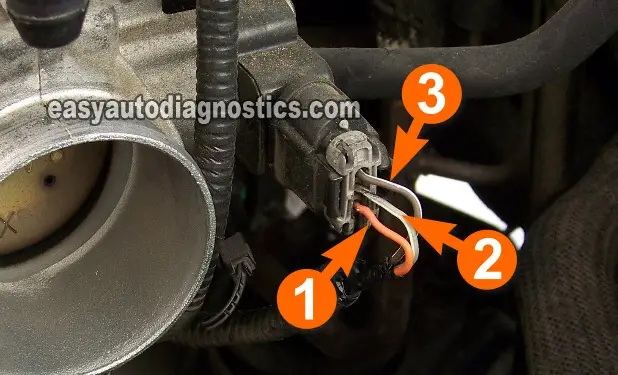
Probe the circuit labeled with the number 2 in the photo with the red multimeter test lead, using an appropriate tool.
- 3
Ground the black multimeter test lead directly on the battery negative (-) terminal.
- 4
Turn the key ON with the engine OFF.
Your multimeter should register about 0.9 to 1 Volt (this voltage specification might vary about ± 1 volt on your Escape or Tribute).
Part 2
- 5
Manually rotate the throttle plate by hand as you eye-ball the multimeter's voltage readings.
- 6
The multimeter's initial voltage reading should increase smoothly as you open the throttle plate to its wide open position (WOT).
- 7
Now, slowly release the throttle plate to its fully closed position, all the while observing the multimeter's reading.
The multimeter's voltage reading should decrease in a smooth and linear fashion.
Part 3
- 8
OK, now have your helper lightly tap the TP sensor with the butt of a screw-driver's handle (or something similar).
- 9
As he or she taps, you need to slowly and smoothly open the throttle to its wide open position and then slowly release it back to its closed position.
All the while you've got your eyes glued on the multimeter to see if the tapping affects the voltage readings. Repeat this (tapping the throttle position sensor) several times to make sure of your results.
Let's examine your test result:
CASE 1: The multimeter registered a smooth increase or decrease in voltage. This is the correct test result and tells you that the TP sensor is working OK and is not the cause of the TPS fault code issue.
If the TPS trouble code keeps coming back, check out the suggestions here: The TPS Code Won't Go Away as to what could be causing the TPS diagnostic trouble code (DTC).
CASE 2: The multimeter DID NOT register a smooth increase or decrease in voltage. This test result tells you that the throttle position is bad only if you have:
- Confirmed that the TPS is getting 5 Volts DC.
- Confirmed that the TPS is getting Ground.
- Confirmed the TPS is not producing a voltage signal that increases/decreases as you open/close the throttle plate.
The TPS Code Won't Go Away
So you've tested the TPS per the instructions in this article and according to the test results, the TPS is good, yet the check engine light is still on. Well, here are a couple of suggestions that might inspire your next diagnostic move:
- The throttle plate's idle-stop screw's factory adjustment has been altered so that the engine could be idled up and mask a miss/misfire and/or rough idle. This increases the TP sensor's signal to the PCM. The PCM doesn't like it and lights up the check engine light (CEL).
- The throttle cable is binding and causing the throttle plate to not fully close.
- This can be verified by simply having someone inside the vehicle pushing the accelerator pedal to the floor and releasing it, with the engine OFF, while you visually check that the throttle plate and cable are not getting stuck somewhere in their travel.
- The TPS is failing intermittently. Which means that it works fine most of the time, but every now and then it doesn't:
- I have found that the best way to test these intermittent problems is to road-test the vehicle with the multimeter hooked up to the TP signal wire with a long wire so that I can comfortably observe the signal going up and down as I or someone else drives.
- The TP sensor's connector is bad, usually the locking tab is broken and the connector has worked itself loose, causing an intermittent false connection.
More 3.0L Ford Escape Tutorials
You can find more 3.0L Ford Escape (Mazda Tribute) tutorials in these indexes:
- Ford 3.0L Index Of Articles.
- Ford 3.0L Index Of Articles (at: troubleshootmyvehicle.com).
Here's a sample of the tutorials you'll find:
- How To Test The Cooling Fan Motors (2001-2004 Ford Escape - Mazda Tribute).
- How To Test The Throttle Position Sensor (2001-2007 3.0L Ford Escape).
- How To Test The Ford Escape COP Coils (Troubleshooting A Misfire).

If this info saved the day, buy me a beer!

