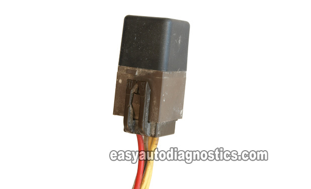
The EEC Power Relay not only supplies battery voltage to the fuel injection computer (also known as the E.E.C. Electronic Control Assembly), but also supplies power to the fuel injectors, the fuel pump relay, and a few other emissions related solenoids.
The EEC Power Relay is easy to recognize because it's usually a brown color. If the EEC Power Relay has already been replaced, you can still recognize it by its brown colored connector.
In this 'how to' tutorial, I'll show you how to test it on your Ford car or pickup in a step-by-step manner.
Just in case you've ever wondered what the heck the acronym E.E.C. stands for, it's: Electronic Engine Control.
Contents of this tutorial:
- What Tools Do I Need To Test The Relay?
- EEC Power Relay Circuit Descriptions.
- Relay Basics: How The EEC Power Relay Works.
- Where To Buy The EEC Power Relay.
- TEST 1: Checking For Power (Low Current Circuit).
- TEST 2: Checking For Power (High Current Circuit).
- TEST 3: Testing The EEC Power Relay Voltage Output.
- TEST 4: Checking The EEC Relay's Ground Circuit.
- Ford EEC Relay Test Summary.
![]() You can find this tutorial in Spanish here: Cómo Probar El EEC Power Relay (Relé De La Computadora De La Inyección Electrónica) (at: autotecnico-online.com).
You can find this tutorial in Spanish here: Cómo Probar El EEC Power Relay (Relé De La Computadora De La Inyección Electrónica) (at: autotecnico-online.com).
EEC POWER RELAY WIRING DIAGRAMS: Need to trace power or Ground? These model-specific diagrams show you exactly how the EEC Power Relay connects to the ECM.
- ECM Power And Ground Circuits Wiring Diagram (1985-1986 5.0L V8 Ford F-Series Pickup).
- ECM Power And Ground Circuits Wiring Diagram (1987 4.9L, 5.0L V8 Ford F-Series Pickup).
- ECM Power And Ground Circuits Wiring Diagram (1988 4.9L, 5.0L, 5.8L Ford F-Series Pickup).
- ECM Power And Ground Circuits Wiring Diagram (1989 4.9L, 5.0L, 5.8L Ford F-Series Pickup).
- ECM Power And Ground Circuits Wiring Diagram (1990-1991 4.9L, 5.0L, 5.8L Ford F-Series Pickup).
EEC POWER RELAY CIRCUIT TESTS: Step-by-step continuity tests to check the wiring between the relay connector, PCM, ignition switch, starter motor relay, and Ground.
NOTE: For your cross reference information, this article will help you test the following EEC Power Relays:
- AutoZone part #:
- Duralast 19840
- O'Reilly Auto Parts part #:
- BWD R648
- AC Delco F1777A
- Others:
- STANDARD MOTOR PRODUCTS Part # RY71T
- STANDARD MOTOR PRODUCTS Part # RY71
- WELLS Part # 19840
What Tools Do I Need To Test The Relay?
You need a few basic things to test the EEC Power Relay and they are:
- Multimeter
- A digital or analog multimeter will work.
- If you need to buy one or are looking to upgrade, check out my recommendations here: Tekpower TP8268 AC/DC Auto/Manual Range Digital Multimeter (Amazon affiliate link).
- Wire Piercing Probe
- This tool is a time saver of the first order. To see what this tool looks like, click here: Wire Piercing Probe.
- Jumper Wires
- You'll need two of them with alligator clips on both ends (you can make these yourself) or you can buy them here: Jumper Wires With Insulated Alligator Clips (Amazon affiliate link).
Disclosure: As an Amazon Associate, I earn from qualifying purchases. Buying through these links helps support this site at no extra cost to you. Thanks for your support —it really means a lot!
EEC Power Relay Circuit Descriptions
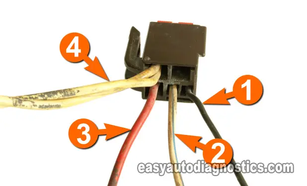
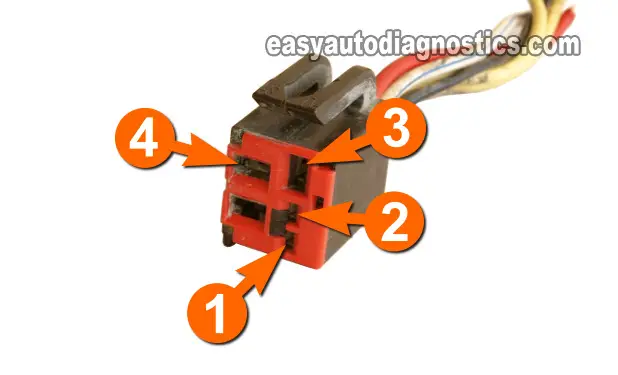
Each of the 4 circuits (wires) of the EEC Power Relay has a specific job to do and these job descriptions are:
IMPORTANT: Your particular Ford vehicle may not have the exact colors listed below. That's not a big deal since the circuit descriptions are the same. You can use the information in this article to diagnose the EEC power relay on your Ford vehicle even if the colors of the EEC power relay connector wires are not the same!
| EEC Power Relay Circuits | ||
|---|---|---|
| Pin | Wire Color | Description |
| 1 | Black * | Chassis Ground |
| 2 | White w/ Light Blue stripe * | Power (from ignition switch) |
| 3 | Red * | Voltage Output |
| 4 | Yellow * | Fused Power (hot all of the time) |
* Your specific Ford vehicle may have different colors.
Relay Basics: How The EEC Power Relay Works
In this section I'll go into a little (and I stress "little") working theory of the EEC power relay to help you better understand what we're going to test in this tutorial.
Every Ford EEC Power Relay has two basic circuits and for the purpose of our discussion, we'll call them:
- A low current circuit.
- This circuit can be identified by the wires labeled with the numbers 1 and 2.
- The low current circuit is the control circuit that 'closes' or 'opens' the high current circuit.
- By 'closing' the high current circuit, I specifically mean allowing voltage to pass thru' the relay (internally) and on its way to the fuel injection computer, fuel injectors, fuel pump relay, etc.
- A high current circuit.
- This circuit can be identified by the wires labeled with the numbers 3 and 4.
- This is the circuit that delivers the voltage (and thus current) to the fuel injection computer (EEC Electronic Control Assembly), fuel injectors, fuel pump relay, etc.
- When the relay is not activated, this circuit is 'open', and as such, does not send any power to anything.
These two circuits are completely independent of each other as the voltage/current flowing through them do not mix.
To get into more specifics, here's what happens when you turn on the ignition key and crank the engine:
- Power (in the form of 10 to 12 Volts) is applied to circuit 2.
- This voltage comes from the ignition switch.
- Power (in the form of 10 to 12 Volts) is always present in circuit 4.
- This voltage comes directly from the battery positive (+) terminal across a fusible link on the starter motor solenoid (on the fender).
- Ground is always present on circuit 1.
- As soon as the ignition switch powers up circuit number 2, the EEC Power Relay closes circuit 3 to circuit 4.
- This causes voltage to reach the fuel pump relay, the fuel injectors, the fuel injection computer, etc. to get power through circuit number 3.
As you can see, it's not all that complicated, and testing the EEC Power Relay isn't complicated either, and I'll show you how in this tutorial.
OK, "working theory" lesson is over, let's get testing in the next page.
Where To Buy The EEC Power Relay
If you need to replace the EEC Power Relay, here are two solid options I recommend —from known automotive brands I've personally used and had good results with on both customer jobs and my own vehicles:
Disclosure: As an Amazon Associate, I earn from qualifying purchases. Buying through these links helps support this site at no extra cost to you. Thanks for your support —it really means a lot!
TEST 1: Checking For Power (Low Current Circuit)

If you read the 'EEC Power Relay Circuit Descriptions', you know there are 2 wires that power the EEC Power Relay.
These two wires are numbered 2 and 4..
Wire labeled with the number 2 supplies 10 to 12 Volts from the ignition switch to the low circuit of the EEC Power Relay.
Circuit 4 feeds the high current circuit of the EEC Power Relay, but we'll check this in TEST 2.
In this test, we'll focus on testing wire number 2 first (this wire is the one that feeds power to the low current circuit).
You can perform this test with or without the EEC power relay connected. OK, this is what you need to do:
- Locate the EEC Power Relay (in the engine compartment) and:
- Remove the black electrical tape and expose the relay's wires.
- Locate the wire that corresponds to circuit number 2.
- With your multimeter in Volts DC mode probe the wire that corresponds to circuit 2.
- You can back probe the EEC Power Relay connector or probe the front of the female terminal.
- NOTE: If you probe the front of the EEC Power Relay's connector, use a very thin probe to avoid damaging the female terminal with regular multimeter test leads.
- Ground the black multimeter test lead directly on the battery negative (-) terminal or on a clean metal spot on the engine.
- Turn the Key On.
- Your multimeter should register one of two things:
- Battery voltage (10 to 12 Volts DC).
- Or no voltage at all.
- When done, turn the Key Off.
OK, let's interpret your test results:
CASE 1: Your multimeter registered 10 to 12 Volts DC. This is good and tells you that the ignition switch (via a fuse) is powering up the low current circuit of the EEC Power Relay.
The next step is to verify that the high current circuit of the EEC Power Relay is also getting battery power. Go to: TEST 2: Checking For Power (High Current Circuit).
CASE 2: Your multimeter DID NOT register 10 to 12 Volts DC. Double check that you're testing the correct wire and repeat the test.
If the multimeter still doesn't register battery voltage (10 to 12 Volts DC) this second or third time around, you need to find out why this voltage is missing.
Although diagnosing this missing voltage is beyond the scope of this tutorial, I can tell you that the ignition switch is the one that provides this power thru' a fuse and this fuse is probably blown.
For a step-by-step guide to testing the wiring between the EEC Power Relay and PCM (written for the F-Series but mostly the same for other models), check out this tutorial:
TEST 2: Checking For Power (High Current Circuit)

In this test step, we're gonna' check that the wire supplying power (10 to 12 Volts DC) to the EEC Power Relay's high current circuit is actually providing that juice.
The wire that provides this juice is the wire labeled with the number 4.
As before, in TEST 1, you can check for this voltage with the EEC Power Relay connected to its connector or not.
OK, to get this test going, this is what you'll need to do:
- Place your multimeter in Volts DC mode.
- With the red multimeter test lead, probe the wire labeled with the number 4.
- You can back probe the EEC Power Relay connector or probe the front of the female terminal.
- NOTE: If you probe the front of the EEC Power Relay's connector, use a very thin probe to avoid damaging the female terminal with regular multimeter test leads.
- Ground the black multimeter test lead directly on the battery negative (-) terminal or on a clean metal spot on the engine.
- Your multimeter should register one of two things:
- Battery voltage (10 to 12 Volts DC).
- Or no voltage at all.
OK, let's interpret your test results:
CASE 1: Your multimeter showed battery power. This is the normal and expected test result.
We now know that the high current circuit of the EEC Power Relay is powered.
The next step is to check/confirm that the EEC Power Relay is sending voltage out from the wire labeled with the number 3. Go to: TEST 3: Testing The EEC Power Relay Voltage Output.
CASE 2: Your multimeter DID NOT show battery power. Recheck all of your multimeter connections and repeat the test one more time.
If the multimeter still doesn't show battery voltage (10 to 12 Volts DC) the second or third time, you need to find out why that voltage is missing.
These 10 to 12 Volts are provided by an inline fusible link (on the starter motor solenoid) or by a mega fuse in the engine compartment fuse box.
The most common cause of this missing voltage is that the inline fusible link or the mega fuse is blown.
If you want to dig deeper into testing the wiring between the relay and PCM, here's a step-by-step tutorial (focused on the F-Series, but useful for most Ford models of this era):


