If the alternator has failed on your 4.6L or 5.4L V8 Ford F-Series pickup, then this is the tutorial you need to test it. The alternator diagnostic test is not hard and the best part is that you'll only need a multimeter for it.
That's right, you don't need any expensive diagnostic test equipment to test the alternator. This is something that you can do and in this tutorial, I'll show you how.
Contents of this tutorial:
- Symptoms Of A Bad Alternator.
- Where To Buy The Alternator And Save.
- TEST 1: Battery Voltage Test With Engine Running.
- TEST 2: Checking Alternator's Battery Output Circuit.
- TEST 3: Making Sure The Voltage Regulator Is Getting Power.
- Location Of The Alternator 175 Amp Mega-Fuse (1997-1998 Pickups).
- Location Of The Alternator Battery Output Fuse (1999-2003 Pickups).
- More 4.6L Ford Test Articles.
APPLIES TO: This tutorial applies to the following vehicles:
- 4.6L Ford F150: 1997, 1998, 1999, 2000, 2001, 2002, 2003.
- 5.4L Ford F150: 1997, 1998, 1999, 2000, 2001, 2002, 2003.
- 4.6L Ford F250 Light Duty: 1997, 1998, 1999.
- 5.4L Ford F250 Light Duty: 1997, 1998, 1999.
Charging System Wiring Diagram: You can find the charging system wiring diagrams that apply to the vehicles covered by this tutorial here:
- Charging System Circuit Wiring Diagram (1997-1998 4.6L, 5.4L V8 Ford F150, F250 Light Duty).
- Charging System Circuit Wiring Diagram (1999-2003 4.6L, 5.4L V8 Ford F150, F250 Light Duty).
E-Series Vans: You can find the alternator test for the E-Series vans here:
- How To Test The Alternator (1997-2003 4.6L, 5.4L Ford E150, E250, E350) (at: troubleshootmyvehicle.com).
Crown Victoria And Grand Marquis: You can find the alternator test for the Crown Vic/Grand Marquis here:
- How To Test The Alternator (1995-2003 4.6L Crown Victoria, Grand Marquis) (at: troubleshootmyvehicle.com).
Symptoms Of A Bad Alternator
The alternator is a key component, of your Ford pickup, that is responsible for two important jobs:
- Charge the battery: The process of cranking and starting the engine puts a heavy load on the battery. This load discharges the battery. It's the alternator's main job to replenish the battery's charge so that it can have enough power to crank and start the engine again.
- Power the accessories: The alternator's other job is to provide the electrical current to all of your pickup's accessories. By accessories I mean everything that has to be (or will be) running once the engine has started. These accessories include components like the fuel pump, windshield wipers, the radio, the fuel injection computer, headlights, brake lights, etc.
So when the alternator fails, you'll see one or several of the following symptoms:
- The charge light (also known as the battery light) will be shining nice and bright on your pickup's instrument cluster.
- Whenever you turn on the headlights (night driving), they glow very dim.
- The engine won't crank. It will only crank and start if you jump start your Ford pickup.
- The only way the engine cranks and starts is if you charge the battery.
- The idle may get high when you come to a stop.
Where To Buy The Alternator And Save
You can buy a brand new alternator for what it will cost you to buy a rebuilt one at your local auto parts store.
Check out the links below and shop/compare and see for yourself:
Disclosure: As an Amazon Associate, I earn from qualifying purchases. Buying through these links helps support this site at no extra cost to you. Thanks for your support —it really means a lot!
Not sure if the above alternator and alternator belt fit you particular Ford pickup? Don't worry, once you get to the site, they'll make sure the parts fit and if they don't they'll ask you about your pickup's specifics to find you the right parts.
TEST 1: Battery Voltage Test With Engine Running

To begin our alternator diagnostics, we'll first check the battery's voltage with the engine running.
More than likely, the battery in your pickup is dead. If it is, charge her up before you start this test.
The battery must be charged enough to crank and start the engine and allow it to stay running for about 5 to 10 minutes.
If you don't have a multimeter or you need to upgrade yours, take a look at my recommendations here: Buying A Digital Multimeter For Automotive Diagnostic Testing.
These are the test steps:
- 1
Crank and start the engine and let it idle.
- 2
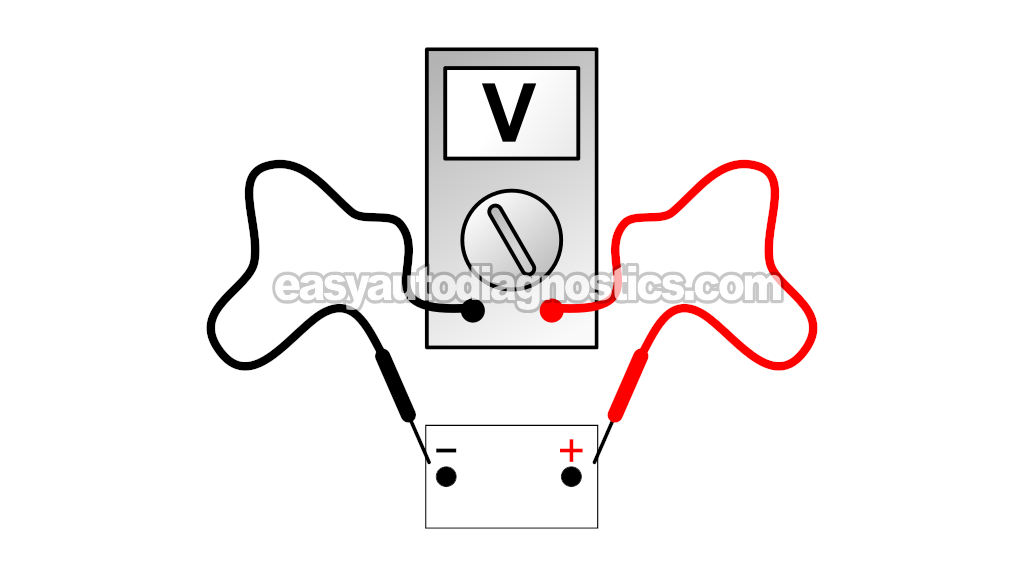
Select Volts DC mode on your multimeter.
- 3
Check the battery's voltage with your multimeter.
- 4
The multimeter should register 13.5 to 14.5 Volts.
If it doesn't, don't worry about this just yet, continue to the next step. - 5
Put an electrical load on the alternator.
You can do this by turning on every accessory possible (inside the vehicle). For example: Turn on the A/C or heater on high, turn on the windshield wipers, turn on the headlights, turn on everything and anything that uses electricity inside and outside of the vehicle. - 6
The multimeter's voltage reading will decrease slightly and then stabilize around 13.5 to 14.5 Volts DC as each accessory comes on.
- 7
Let the engine run for about 5 minutes with all of the accessories on.
- 8
The battery voltage should remain between 13.5 to 14.5 Volts DC with all of the accessories on during the whole 5 minute duration.
OK, let's interpret your multimeter test results:
CASE 1: Your multimeter registered 13.5 to 14.5 Volts. This test result confirms that the alternator is charging the battery and providing for the electrical needs of your pickup's accessories. Since the alternator is good (not defective), no further testing of the alternator is needed.
Now, if you're having to jump-start the pickup to get it going, this test result points to a bad battery or a parasitic drain. A parasitic drain is tech-speak for something staying on (usually inside the pickup, for example: a dome-light) and draining the battery while the engine is off.
CASE 2: Your multimeter registered a voltage that steadily dropped down to 9 Volts. This multimeter voltage test result lets you know, beyond a shadow of a doubt, that the alternator is not charging the battery.
Before we can conclude that the alternator is fried and needs to be replaced, we need to do one more test. For this test go to: TEST 2: Checking Alternator's Battery Output Circuit.
TEST 2: Checking Alternator's Battery Output Circuit

In this test section, we're gonna test the battery output circuit of the alternator. Specifically, we need to make sure that the alternator's output can actually reach the battery.
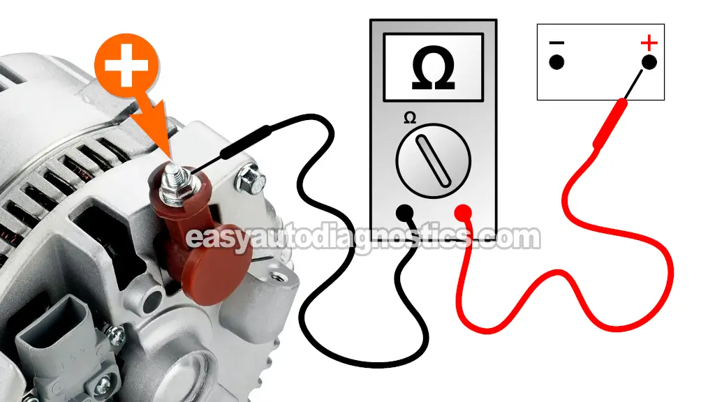
This test simply involve testing the continuity of the thick cable that connects to the back of the alternator with a nut.
In the illustration above, the red multimeter test lead points to this location. All of the alternator's output (current and voltage) reaches the battery via the cable that connects to this threaded stud.
Before the alternator's output reaches the battery via this cable, it has to go through two fusible links (1999-2003 pickups) or a 175 Amp mega fuse (1997-1998 pickups).
It's not uncommon for the fusible link (or mega fuse) that protects this circuit gets blown. Because testing this battery output circuit is pretty easy and fast, in this section, we're gonna' to focus on confirming that it's okay.
The fastest and easiest way to check to see if this circuit is OK is by checking its continuity. This continuity test is done with a multimeter in Ohms mode.
NOTE: The 1997-1998 Ford F-Series pickups use a 175 amp mega fuse. The 1999-2003 Ford F-Series pickups use two 12 gauge inline fusible links.
This is what you'll need to do:
- 1
Disconnect the battery negative (-) cable from the battery but leave the positive (+) cable connected to the positive (+) post.
IMPORTANT: Do not proceed to the next steps until you have done this first. - 2
Set your multimeter to Ohms mode.
- 3
Connect the red multimeter test lead to the stud shown in the photo above.
A BLK/ORG cable connects to the stud indicated by the arrow (in the photo above).
NOTE: Don't disconnect the BLK/ORG cable from the alternator. - 4
Connect the black multimeter test lead on the battery positive (+) terminal (at the battery).
The battery negative (-) wire must remain disconnected from the battery. - 5
Your multimeter will register one of two values:
1.) Continuity (usually an Ohms value of about 0.5 Ohms).
2.) No continuity (an infinite Ohms reading (OL)).
Let's take a look at what your test results mean:
CASE 1: Your multimeter confirms that the circuit has continuity. This test result tells you that the mega fuse or inline fusible link is OK. In other words, if the alternator were working and charging, all of its charge would actually reach the battery.
Your next step is to make sure that the alternator's voltage regulator is getting power. For this test go to: TEST 3: Making Sure The Voltage Regulator Is Getting Power.
CASE 2: Your multimeter confirms that the circuit DOES NOT HAVE continuity. This test results let you know that the alternator's charge is not reaching its destination -the battery.
Your next step is to replace the 175 amp mega fuse (1997-1998 pickups) or the 12 gauge in-line fusible link (1999-2003 pickups) to resolve the alternator's no charge problem.
If your pickup is a 1997-1998 year model, you can see the location of the 175 Amp mega-fuse here: Location Of The Alternator 175 Amp Mega-Fuse (1997-1998 Pickups).
If your pickup is a 1999-2003 year model, you need to check the 12 Gauge grey inline fusible links located at the starter motor relay.


