TEST 4: CKP Sensor Signal Test
So far you have confirmed that:
- The ignition module is getting power (12 Volts).
- And that it's two Ground paths are OK.
The next step is to test the crankshaft position sensor.
The crankshaft position sensor is an analog type, which means it has two wires and can be tested with a multimeter in AC Volts mode.
One last thing, you need to do this test with a fully charged battery since this will have a direct impact on your multimeter AC voltage readings (what you want is the engine to crank as fast as possible).
These are the test steps:
- Place your multimeter in Volts AC mode.
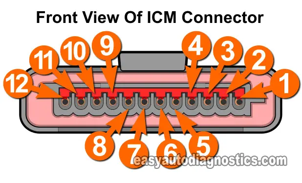
- With an appropriate tool (like a wire piercing probe), pierce the wire labeled with the number 4 (in the image viewer photo) and connect one of the multimeter leads to it.
- With an appropriate tool (like a wire piercing probe), pierce the wire labeled with the number 5 (in the image viewer photo) and connect the remaining multimeter lead to it.
- Crank the engine (when all of the connections are set).
- Your multimeter should read 0.7 to 0.9 Volts AC the whole time the engine is cranking.
- The voltage numbers will not stay fixed and this is normal since they'll fluctuate a little with the cranking speed of the starter motor.
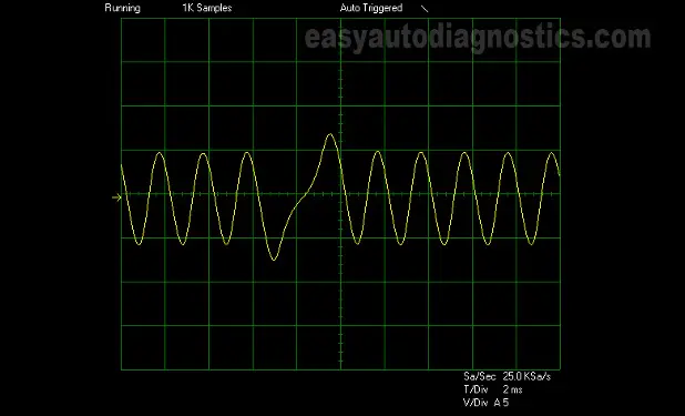
- If you're using an Oscilloscope, the waveform should look like the one in image 2 of 2 in the image viewer.
Let's take a look at what your test results mean:
CASE 1: The multimeter registered the indicated AC Volts. This result confirms that the ignition module is being fed with the crankshaft position sensor signal.
There's still one more test to do (before condemning the ignition module as bad), and this is to make sure that the ignition module is now activating the ignition coil packs. Go to: TEST 6: Switching Signal Test (No Start).
CASE 2: You DID NOT get the indicated AC Volts. This result exonerates the ignition module as bad. After all, without the crankshaft position sensor signal it's not gonna' start activating the ignition coil and the PCM is not gonna start injecting fuel.
TEST 5: Checking The Ignition Coil Driver Signals
Having one of the ignition coil driver circuits (inside the ignition control module) fail is the most common problem with this type of ignition system set up.
Usually, but not always, when this happens, the PCM will set one of the following diagnostic trouble codes:
- P0350 Ignition Coil Primary Circuit Malfunction.
- P0351 Ignition Coil Primary A Circuit Malfunction (Coil Driver for Cylinders 1 and 6 Malfunction).
- P0352 Ignition Coil Primary B Circuit Malfunction (Coil Driver for Cylinders 3 and 5 Malfunction).
- P0353 Ignition Coil Primary C Circuit Malfunction (Coil Driver for Cylinders 7 and 4 Malfunction).
- P0354 Ignition Coil Primary C Circuit Malfunction (Coil Driver for Cylinders 2 and 8 Malfunction).
When this happens, you'll have two dead ‘Paired Cylinders’ (due to a lack of spark) because the ignition module's coil driver can't activate the ignition coil (within the coil pack) that feeds those two cylinders with spark.
- In case you weren't aware, it's the ignition coil drivers (inside the module) that are responsible for creating the switching signals that the ignition coils (within the coil pack) need to start sparking away.
The other thing you'll notice, is two specific misfire codes (although not in every single case).
OK, this is what you need to do:
- Connect the alligator clip of your 12 Volt test light to the battery positive (+) terminal.
- It's important that you use a simple and unpowered automotive 12 Volt test light.
- Probe one of the following wires with the metal probe end of the 12 V. test light (depending on what cylinders are dead):
- Wire number 8 (if Cylinders #1 and #9 are dead).
- Wire number 9 (if Cylinders #3 and #5 are dead).
- Wire number 11 (if Cylinders #4 and #7 are dead).
- Wire number 12 (if Cylinders #2 and #8 are dead).
- Have your helper crank the engine (when all is set).
- The 12 Volt test light should blink ON and OFF as the engine cranks.
- Whatever the 12 V. test light does when you turn the key ON (and before you crank the engine) does not matter. What matters is what it does when you crank the engine.
Let's take a look at what your test results mean:
CASE 1: The 12 Volt test light blinked ON and OFF. This result confirms that the ignition control module (ICM) coil's driver (for those 2 ‘Paired Cylinders’) is creating the switching signal.
Now, if you're not getting spark from the two ‘Paired Cylinders’ this particular switching signal activates, then the ignition coil is bad and needs to be replaced to solve the diagnostic trouble codes and the misfire condition.
CASE 2: The 12 Volt test light DID NOT blink ON and OFF. This result confirms that the ignition module's coil driver (for those 2 ‘Paired Cylinders’) is bad. Replace the ignition control module (ICM) to solve the problem.
TEST 6: Switching Signal Test (No Start)
So far you have confirmed that:
- You have a 'no-spark no-start' condition.
- The ignition module is getting power (TEST 1).
- That it's two Ground paths are OK (TEST 2).
- And that the crankshaft position sensor signal is present (TEST 4).
The next step is to test that the ignition control module is creating 4 switching signals.
The switching signals are the ones that activate the coil packs to start sparking away.
These are the test steps:
- Connect the alligator clip of your 12 Volt test light to the battery positive (+) terminal.
- It's important that you use a simple and unpowered automotive 12 Volt test light.
- Probe one of the following wires with the metal probe end of the 12 V. test light (you'll test them all, but one at a time):
- Wire number 8 (Switching Signal for Cylinders #1 and #9).
- Wire number 9 (Switching Signal for Cylinders #3 and #5).
- Wire number 11 (Switching Signal for Cylinders #4 and #7).
- Wire number 12 (Switching Signal for Cylinders #2 and #8).
- Have your helper crank the engine (when all is set).
- The 12 Volt test light should blink ON and OFF as the engine cranks.
- Whatever the 12 V. test light does when you turn the key ON (and before you crank the engine) does not matter. What matters is what it does when you crank the engine.
- Repeat the above test in the next indicated wire in step 2.
Let's take a look at what your test results mean:
CASE 1: The 12 Volt test light DID NOT blink ON and OFF. This result confirms that the ignition control module (ICM) is bad and needs to be replaced.
Here's the reason why: So far you've confirmed that the ICM is getting power and Ground. You've also confirmed the crankshaft position sensor signal. If all these are present, then it has to create all 4 switching signals. Since it's not, the module is bad.
CASE 2: There is no Case 2.
Related Articles
You can find a complete list of 4.6L 'how to articles in the: Ford 4.6L, 5.4L Index Of Articles.
Here's a small sample of what you'll find in the index:
- How To Test The 4.6L, 5.4L Coil-On-Plug Ignition Coils.
- How To Test The 4.6L, 5.4L EGR Valve.
- How To Test The 4.6L, 5.4L MAF Sensor.
- How To Clean The 4.6L, 5.4L MAF Sensor.

If this info saved the day, buy me a beer!


