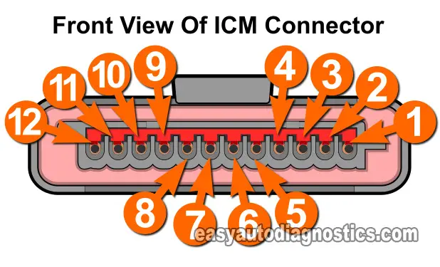
TEST 1: Checking For Power
The very first thing that you and I need to check is that the ignition control module is getting juice.
If you're just coming into this article and haven't read the section: Where To Start The ICM Diagnostic, please do so now, since this test may not apply to you.
OK, if this test does apply to you and you're testing a 'no-start no-spark no-fuel-injector-pulse' condition, the most logical starting point is checking the basics. This means verifying that the ignition module is getting juice (12 Volts).
OK, to get this show on the road and to get to the bottom of problem, this is what you need to do:
- Place your multimeter in Volts DC mode.
- With an appropriate tool (like a Wire-Piercing Probe), pierce the wire labeled with the number 6 (in the image viewer photo).
- Connect the red multimeter test lead to this tool.
- Connect the black lead of your multimeter to battery Ground.
- Turn the key ON (but engine OFF).
- Your multimeter should read 10 to 12 Volts DC.
Let's take a look at what your test results mean:
CASE 1: You got 10 to 12 Volts. This result confirms that the ignition module is getting juice. The next step is to verify that these 12 Volts have a good Ground path. Go to TEST 2: Checking The Ground Circuit.
CASE 2: You DID NOT get 10 to 12 Volts. This result exonerates the ignition module as bad. After all, without power it's not gonna' work!
Although it's beyond the scope of to check why these 10 to 12 Volts are missing, you have at the least eliminated the ignition module as the cause of your car's 'no-start no-spark' condition.
TEST 2: Checking The Ground Circuit
So far, in your testing, you've confirmed that the ignition control module (ICM) is getting power (12 Volts).
The next step is to make sure that the ICM has a good Ground path and this section will help you with this.
Before we start, let me tell you that the ignition module has two wires that provide it with a path to Ground and they are:
- Wire labeled with the number 7.
- Wire labeled with the number 10.
Here's what you'll need to do:
- Place your multimeter in Volts DC mode.
- With an appropriate tool (like a wire piercing probe), pierce the wire labeled with the number 7 (in the image viewer photo).
- Connect the Black lead of your multimeter to this tool.
- Connect the red multimeter test lead to the battery positive (+) terminal.
- Turn the Key On (but Engine Off).
- Your multimeter should read 10 to 12 Volts.
- Repeat the above steps on the wire labeled with the number 10.
Let's take a look at what your test results mean:
CASE 1: The multimeter registered 10 to 12 Volts. This result confirms that the ignition module is getting plenty of Ground.
The next step is to see if the ignition module is getting the crankshaft position sensor signal. For this test, go to: TEST 4: CKP Sensor Signal Test.
CASE 2: The multimeter DID NOT register 10 to 12 Volts. This result exonerates the ignition module as bad and tells you that the reason for your no-start condition is a lack of Ground.
Repair the Ground issue and retest.
TEST 3: Checking The PIP Signal
When the PIP signal is missing, your car is not gonna' start.
But more specifically, it won't start because the PCM isn't pulsing the fuel injectors, although spark is present in all of the spark plug wires.
This is because the PCM needs the PIP signal from the ignition module to start activating the fuel injectors, but the module only needs the crankshaft position sensor signal to start activating the ignition coils to spark.
An ignition module going bad and not creating the PIP signal is rare, but it does happen. So, if you suspect that the PIP sensor is bad, you need to make sure that:
- You have checked the fuel injector pulses with a Noid light and confirmed that there are NO PULSES.
- And that you have checked for spark and confirmed that there is spark.
If the fuel injector and spark test results don't meet the two above conditions, this test is NOT gonna' help you. Simply put, if the PCM is pulsing the fuel injectors, the PIP signal is present.
One last thing, the ignition control module has to be connected to its electrical connector for this test to work.
OK, this is what you need to do:
- Connect the red lead of the LED to the wire labeled with the number 1.
- This is the wire that delivers the PIP signal to the PCM.
- Connect the black lead of the LED to a good Ground or directly on the battery negative (-) terminal.
- Have your helper crank the engine (when all is set).
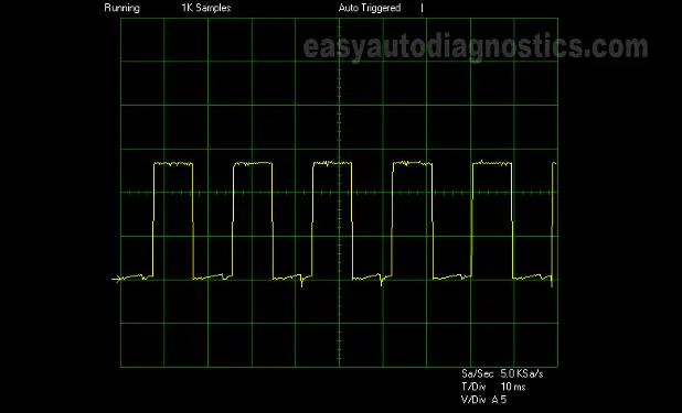
- The LED light should blink ON and OFF as the engine cranks.
- Whatever the LED light does when you turn the key ON (and before you crank the engine) does not matter. What matters is what it does when you crank the engine.
- If you're using an oscilloscope, the waveform should look like the one in image 2 of 2 in the image viewer.
Let's take a look at what your test results mean:
CASE 1: The LED light blinked ON and OFF. This test result confirms that the ignition control module (ICM) is creating the PIP signal.
This test result also indirectly confirms that the crankshaft position sensor is OK too, since without the crank signal there would be no PIP signal.
So, if the no-fuel-injector-pulse condition is still present, you'll need to check that:
- The fuel injectors are getting power (12 Volts).
- That the PIP signal wire is does not have an ‘open-circuit’ problem between the ICM and the PCM.
Although testing the two above conditions is beyond the scope of this article, you at least now know where your troubleshooting needs to focus on.
CASE 2: The LED light DID NOT blink ON and OFF. This test result confirms that the ignition module is bad if, the two conditions above (no fuel injector pulses and spark is present) are met.


